I agree with Hans that he has confirmed validity of his model by comparing it to measurements made with a test recording. As such, to me, the model seems correct.
This bit seems not to have been tried so far. I see loading to the 75 us time constant and trying to damp the peak by increasing C_load, rather than varying R_load to dampen the peak as Bob has suggested.
One thing I suggest going forward to evaluate damped cartridge loading is to not use the damping to load the cartridge to the point where the cartridge and its loading alone provide the 75 us time constant, but rather use the loading resistance only to the extent that it sifficiently damps the resonance to the point where it results in a response that is reasonably close to a first order rolloff.
This bit seems not to have been tried so far. I see loading to the 75 us time constant and trying to damp the peak by increasing C_load, rather than varying R_load to dampen the peak as Bob has suggested.

Bob,Hi Hans,
I'm sorry that my reply had been so long, and perhaps some of my points were unclear or misinterpreted in the clutter. I'll take a look more closely when I get a chance and give a longer reply. In the meantime, please read Rod Elliot's piece that I referred to if you have not already. Please also take another look at my lenthy response.
Briefy, however, I did not intend to say that your model was wrong or did not include effects due to eddy current. The resistors that you put in parallel with your 3 coils do take account of eddy current in causing the generator model to have decreasing impedance with frequency. As far as I know, you models are correct in modeling the effect of eddy currents on the impedance.
I'm just saying that the way that you used your generator impedance models in your simulations did not take account of the eddy current losses in signal as frequency increases that occur. My comments in that regard are based on theory and what Rod Elliott said.
I do understand that it can be difficult to separate things out, given the presence of cantilever response in a real cartridge.
Best regards,
Bob
Thx for your reply.
I have no intention to disqualify Rod's attempts to giving some more insight in a Cart's behavior.
But what I don't understand is why you give this paper an elevated value where Rod used just a 1V source connected via a 47K resistor to the Cart's generator.
His measurement in green went only from 100Hz to 20Khz and only measured level and no phase and deviated from the simulated model in the higher frequency range, already showing the imperfection of his model.
According to his explanation, dividing the inductance in two sections had to be done because of eddy currents.
In my case I used a Voltage Network Analyzer measuring up to 1Mhz that produced way more information than Rod's tests.
See both examples below.
And I did not test with just one voltage but with a set of different voltages, all giving practically the same result, showing that no saturation effects had to be taken into account.
So the generated replacement models for the generators can be regarded as level independent, let's say within a few percent accurate, where my models with four induction sections do not deviate up to 1Mhz from the measurements.
Following Rod's explanation of the impact of Eddy current, this implies that my models now fully include and integrate the effects of eddy current up to 1Mhz, but also that the models are level independent !
So I have no idea what you mean when mentioning that eddy currents are not taken into account.
At the same time, when considering the complete model for a given Cart as a black box, and when proving it´s transfer to being accurate and exact to a real life recording on a calibrated recording chain, independent of load, it really should not be an issue what´s inside the black box, and what (eddy) currents are doing, does it ?
But in this case what´s inside the black box was even explained in great detail.
Hans
Please have a look at #154 where the 8Khz or 20usec pole was used.I agree with Hans that he has confirmed validity of his model by comparing it to measurements made with a test recording. As such, to me, the model seems correct.
This bit seems not to have been tried so far. I see loading to the 75 us time constant and trying to damp the peak by increasing C_load, rather than varying R_load to dampen the peak as Bob has suggested.
Hans
Hi Hans,
Let's talk about eddy current, and see what we agree on or disagree on. This is only one piece of the discussion, but it is an important one.
I'll make some assertions about eddy current and its effects, and you can let me know if you agree or disagree, and also add what you think.
Consider a simple inductor exposed to a changing magnetic field. That changing magnetic field is the input signal. In addition to loss from its DC resistance, it has eddy current losses resulting from its core. The changing magnetic field induces current flow in the core. That current flow creates a magnetic field that opposes the magnetic field that is incident on it and the coil. The result is loss.
The eddy current loss can be modeled by a resistor shunting the ideal inductor. That is the reason that you (and Rod) have a resistor across an inductor in your models. It is also the reason why the impedance (and measured inductance) decreases as frequency increases.
If there was no eddy current effect, there would be no reason for the resistors across the inductors in the model.
The ideal inductance creates an EMF signal due to the changing magnetic field to which it is exposed. Call that the open-circuit voltage. The resistor that we placed across the inductor in the model forms a low-pass filter with the ideal inductance, reducing signal output across the coil.
In the real world, that reduction in signal across the coil is the result of a reduced magnetic signal field impinging on the coild due to opposition to the incoming magnetic field that originales from eddy effect, as described above.
One more thing about eddy current. It should not be confused with core saturation effects. Eddy current effects are fairly linear small-signal effects. Eddy current effects exist in the total absence of saturation.
If I have this wrong, please let me know in what way these assertions are wrong (and how we correct or revise them). It will be helpful if we have (or work toward) a common understanding of this aspect of the discussion.
Cheers,
Bob
Found the article at last, Had the name spelled wrong,
B. I. Hallgren, “On the noise performance of a magnetic phonograph pickup”, JAES, Sept. 1975
B. I. Hallgren, “On the noise performance of a magnetic phonograph pickup”, JAES, Sept. 1975
Hi Bob,Hi Hans,
Let's talk about eddy current, and see what we agree on or disagree on. This is only one piece of the discussion, but it is an important one.
I'll make some assertions about eddy current and its effects, and you can let me know if you agree or disagree, and also add what you think.
Consider a simple inductor exposed to a changing magnetic field. That changing magnetic field is the input signal. In addition to loss from its DC resistance, it has eddy current losses resulting from its core. The changing magnetic field induces current flow in the core. That current flow creates a magnetic field that opposes the magnetic field that is incident on it and the coil. The result is loss.
The eddy current loss can be modeled by a resistor shunting the ideal inductor. That is the reason that you (and Rod) have a resistor across an inductor in your models. It is also the reason why the impedance (and measured inductance) decreases as frequency increases.
If there was no eddy current effect, there would be no reason for the resistors across the inductors in the model.
The ideal inductance creates an EMF signal due to the changing magnetic field to which it is exposed. Call that the open-circuit voltage. The resistor that we placed across the inductor in the model forms a low-pass filter with the ideal inductance, reducing signal output across the coil.
In the real world, that reduction in signal across the coil is the result of a reduced magnetic signal field impinging on the coild due to opposition to the incoming magnetic field that originales from eddy effect, as described above.
One more thing about eddy current. It should not be confused with core saturation effects. Eddy current effects are fairly linear small-signal effects. Eddy current effects exist in the total absence of saturation.
If I have this wrong, please let me know in what way these assertions are wrong (and how we correct or revise them). It will be helpful if we have (or work toward) a common understanding of this aspect of the discussion.
Cheers,
Bob
I agree with every word you say, there is no disagreement whatsoever and I'm happy that we can discuss it in this civilized way.
It seems that we can agree that all separate inductor sections in parallel to a resistor are there to model the effects of Eddy current.
Where we differ in looking at the Generator is that I am looking at the Generator's transfer curve as a given fact without any room for guesswork, where you seem to have the desire to understand the background why the replacement model came out in it's current form.
This background is interesting indeed and of vital importance for a Cart manufacturer, but for a replacement model when regarded as a black box it was of second order importance for me.
My focus was fully oriented on getting a transfer curve for the Cantilever assembly, where I went in much more detail.
So when we can agree that the effects of eddy current are fully taken care of in the model, I don't see any reason why this subject can't be put to rest.
When a Cart's behavior can be predicted in the finest detail within almost +/- 0.1dB from 100Hz up to 30Mhz, fully independent from external load termination, what could an already compensated Eddy current possibly still add to this.
Maybe you could explain your concerns in more detail, preferably supported by physical evidence.
Hans
Hi Hans,
That's good to hear.
Now that we agree on the behavior of an inductor with loss due to eddy current and modeled with a shunt resistor across an ideal inductor, let me explain my concern.
Let's for the moment treat that inductor as the cartridge, knowing that it is a highly simplified model. As we have said, the impedance of that inductor, as compared to an ideal inductor of the same low-frequency value, will decrease as frequency increases. If we model the cartridge with that lossy inductor by feeding it from a voltage source at one end and loading it to ground through a load resistor and maybe a shunt capacitance, the lossy nature of the inductor will cause the output to increase with frequency as compared to a cartridge with a lossless inductor. This can lead to a rising frequency response as a result of the losses created by the eddy current (as compared to the same experiment with a coil with no eddy current loss). This I'll call the series model where the cartridge is in series with an input signal that is a test voltage source.
Now let's rotate the lossy inductor 90 degrees into a vertical position with the bottom grounded and the top being the output, which is loaded in the same way to ground, but here make the input signal a changing magnetic field, just as in a real cartridge. In this case, the presence of the eddy current loss results in an output that falls with increasing frequency as compared to what would come out if there were no eddy current losses.
This is where I'm scratching my head and wondering if modeling the system (voltage source, series cartridge inductance and shunt load) with a test voltage source at the input end is giving us an inaccurate answer in the presence of eddy current losses. I'm thinking that the eddy current, which has been modeled by a resistance across the coil, is giving us a bit of a high-frequency boost in the simulation that is not really there. It makes me think that in this simulation, the loss in EMF caused by the eddy current reducing the effective magnetic signal field at high frequencies is not being properly taken into account.
Cheers,
Bob
Hi Bob,
Your concerns would have been reflected in the recordings, wouldn't it, but they aren't and there's a simple reason why.
That's because of the (Lorenz) reciprocity theorem for passive circuits, see below.
From Wikipedia, the free encyclopedia
Reciprocity in electrical networks is a property of a circuit that relates voltages and currents at two points. The reciprocity theorem states that the current at one point in a circuit due to a voltage at a second point is the same as the current at the second point due to the same voltage at the first. The reciprocity theorem is valid for almost all passive networks. The reciprocity theorem is a feature of a more general principle of reciprocity in electromagnetism.
So forcing a voltage in the Generator from one end will include all the same eddy current influences as when forced from the other side.
But in the end the most convincing are the hard facts acquired from the recordings.
And for your information, those recordings are all done by an independent person in Norway, far away from me, in this case Dagfinn Rasmussen.
To my opinion adding all together should take away any reason for further concern about the validity of the Cart model.
Hans
Last edited:
While trying hard to understand this discussion, I'm wondering if it revolves around reciprocity, which only applies to linear conversions. Is this detail of eddy currents linear, and therefore reciprocal? Much thanks for any clarification.
All good fortune,
Chris
All good fortune,
Chris
ps: I would suggest that the levels of disagreement are too far below the unknown (but guess-able) levels of test disk reliability, especially at high frequencies, for them to be trusted. Angels dancing on the heads of pins, that kinda thing.
All good fortune, and much thanks for the fascinating and informative discussion,
Chris
All good fortune, and much thanks for the fascinating and informative discussion,
Chris
Hi Chris,
When you look at the Generators replacement diagram, where the effect of eddy currents is fully covered by resistors in parallel to Inductors, you only have linear components, so yes, reciprocity should apply for the full 100%.
Hans
When you look at the Generators replacement diagram, where the effect of eddy currents is fully covered by resistors in parallel to Inductors, you only have linear components, so yes, reciprocity should apply for the full 100%.
Hans
I should probably have phrased my question as "does actual eddy current effect fit your model?" to the extent that it scales linearly, and your tests at multiple levels seems to support that. In that case, I'm lost and can't follow the argument trail.
Could a bystander ask that we stop using the term "cantilever effects" when the actual second resonance mechanism is the stylus effective mass x vinyl compliance resonance? Cantilever mass does contribute, but doesn't necessarily dominate.
Much thanks, as always,
Chris
Could a bystander ask that we stop using the term "cantilever effects" when the actual second resonance mechanism is the stylus effective mass x vinyl compliance resonance? Cantilever mass does contribute, but doesn't necessarily dominate.
Much thanks, as always,
Chris
A very quiet admission from me:
the system is not an unknown system of control engineering and mechanical engineering , i.e. a multi-mass oscillator /"Mehrmassenschwinger". This system is 100% modelable. I don't understand why there is a dispute over competence here.
Hans 👍,
great work.
thx Chris ...
the system is not an unknown system of control engineering and mechanical engineering , i.e. a multi-mass oscillator /"Mehrmassenschwinger". This system is 100% modelable. I don't understand why there is a dispute over competence here.
Hans 👍,
great work.
thx Chris ...
I can’t follow it either.I should probably have phrased my question as "does actual eddy current effect fit your model?" to the extent that it scales linearly, and your tests at multiple levels seems to support that. In that case, I'm lost and can't follow the argument trail.
But I can fully understand that when your damped brainchild is turning out not to bring what was expected, it takes some time to accept the facts.
In this very case it’s a clash of facts against concerns.
Very true, it’s a mix of different mechanisms where none of them is really dominant.Could a bystander ask that we stop using the term "cantilever effects" when the actual second resonance mechanism is the stylus effective mass x vinyl compliance resonance? Cantilever mass does contribute, but doesn't necessarily dominate.
Hans
P.s. I think that meanwhile the Eddy current discussion can be safely closed.
Given that it's Bob Cordell raising the question, I'm reluctant to dismiss it out of hand. Could we agree that all of these models ignore geometric losses arising from non-zero stylus dimension in the plane of travel and stylus ETM x vinyl compliance resonance, and so will not conform to real playback? (Or at least be critically dependent on the stylus/groove wall interface, so not general).
Could I interpret Bob Cordell's reservations as being about the way the actual generator is applied in all extant models advanced enough to include eddy current effects? If so, it seems reasonable to raise the question.
Much thanks, and all good fortune,
Chris
ps: Back in the mid-1970s I thought I had a great idea, to make the 75uS pole by LR with a suitable loading resistor, and wrote to Ed Dell for comment (this was way before the Internet). He wrote back that he'd run it by his expert, who said only "Lighter loading is better." I later found out that the idea was already in some National Semiconductor handbooks, so nothing new under the sun.
Hi Chris,
I agree that knowledgeable people like Bob deserve full attention in cases of questions.
But we can´t simply neglect that for at least 10 Carts, all having completely different internals and Cantilever assemblies, that for all models the models coincide with the recordings.
I agree that knowledgeable people like Bob deserve full attention in cases of questions.
But we can´t simply neglect that for at least 10 Carts, all having completely different internals and Cantilever assemblies, that for all models the models coincide with the recordings.
Chris,Could we agree that all of these models ignore geometric losses arising from non-zero stylus dimension in the plane of travel and stylus ETM x vinyl compliance resonance, and so will not conform to real playback? (Or at least be critically dependent on the stylus/groove wall interface, so not general).
No we can't agree.
The mechanical response started by subtracting the Generators response from the recorded overall response and must therefore include everything that contributes.
To construct the replacement model having exactly that response, the geometrics of tip, it's equivalent mass, position on and speed of the test record and Vinyl properties are all fully taken into account.
Did you read the the paper in detail and the references to Bastiaans, it almost seems you still have to.
Like for the electrical part, if these details hadn´t been meticulously included in the model, it would have been most likely impossible to get a match within +/- 0.1dB between model and recording for all those Carts having completely different pole geometry, cantilever assemblies, tips and equivalent tip masses.
Could I interpret Bob Cordell's reservations as being about the way the actual generator is applied in all extant models advanced enough to include eddy current effects? If so, it seems reasonable to raise the question.
Here the answer is the same as above.
When the effects of eddy current hadn't been fully covered in the model, matches of +/- 0.1dB between model and recording would have been impossible.
And the reciprocity theorem in this case confirms the validity of the way of constructing the generator's model, after having measured it from 100Hz to 1Mhz.
But when something in the Models is still missing, its contribution must be less than +/- 0.1dB an can be safely be disregarded for that reason.
Just a discussion without facts whether certain elements are missing, incomplete or misinterpreted can go on and on forever and don't solve anything other than supposing that the models may be questionable.
It's beyond my imagination that when model an recording are that accurate over a large BW and independent of load, that something may be still questionable.
IMO the only proof of the pudding is in the eating.
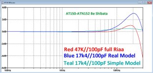
So let's start where the discussion began, being the unbelief that a 8Khz damping raises the high end of the spectrum instead of flattening it and that it complete deviates from a simple model of just Lcart and Rcart terminated with a 8Khz pole.
So I invite anyone to do the same test as in the attachment, recording from 100Hz to 30Khz with a 47K termination and with a 8Khz termination.
Hans
P.S. when having problems in making the graphics, when sending me the .wav files of the recordings I can turn this into an image,
Attachments
- Home
- Source & Line
- Analogue Source
- Bob Cordell's VinylTrak