the stepped delay element just tests the "robustness" of the loop gain "picture" implied stability - shows a unwelcome stability "surprise" if you rely on just measuring the global loop gain with TMC
once you know that the "simple Middlebrook" loop gain probe "inside" the TMC loops gives a "fair" picture of stability then you can just use it by itself
as I do when I keep pointing to the essential similarity of TMC and 2-pole compensation
due to the potential for "linearizing" the diff pair due to higher gain I prefer 2-pole - and the global loop gain measurement gives good stability indication
Then how would you set it up to use the middlebrook probe inside the TMC loops?
Could you show an example of how you usually do it?
On a real amplifier simulation.
Last edited:
........once you know that the "simple Middlebrook" loop gain probe "inside" the TMC loops gives a "fair" picture of stability then you can just use it by itself
as I do when I keep pointing to the essential similarity of TMC and 2-pole compensation
due to the potential for "linearizing" the diff pair due to higher gain I prefer 2-pole - and the global loop gain measurement gives good stability indication
I tried repeatedly to convince bob cordel and others of this and failed.
my "BobAmp" subcircuits are pretty complete examples from Bob's book/this thread - I just wrapped them up in a "op amp" symbol to keep my compensation sims readable
when you open my sim, run in Ltspice you can also view the "op amp" BobAmp .asc to see what's inside
when you open my sim, run in Ltspice you can also view the "op amp" BobAmp .asc to see what's inside
my "BobAmp" subcircuits are pretty complete examples from Bob's book/this thread - I just wrapped them up in a "op amp" symbol to keep my compensation sims readable
when you open my sim, run in Ltspice you can also view the "op amp" BobAmp .asc to see what's inside
So you basically just have to use standard middlebrook probe but with the TMC resistor connected inside the loop? What about the weird phase dip you get with the TMC resistor connected inside the loop, should it really look like that?
What is the circuit between out_tmc and d_tmc for? Is that needed as well?
EDIT : The circuit is just the delay you added, it should be ignored, right?
EDIT#2 : Another thing, how would you then simulate OLG with the TMC resistor inside the loop?
EDIT#3 : Looks like the 0 degrees point on your plots is the point where you get positive gain, how did you set the plots up for that? It is usually the -180 degrees point that shows when you get positive gain. Do you have to look at it differently due to the phase swings the simulation shows with the TMC resistor inside the loop?
EDIT# : Phase starts out at around +180 degrees, is that why the 0 degrees point is now considered the point where you get positive gain? Secondly, can we count on the phase it shows using this method?
Last edited:
the delay can be deleted, tmc_d is just the delyed output, need to settle on just one of _c, _d when you remove the delay
the phase dip is unavoidable with the higher order loop gain - you will see it with 2-pole global loop gain as well as TMC measured "inside" both loops
once you have the simple Middlebrook or Tain LoopGain probes the open loop gain is less interesting - the huge inductor feedback isolation can give incorrect results where AC loading is important - the Tain probe is better
either Middelbrook or Tain probes in just the outer loop still measure the "global" feedback in that loop - just don't give a good indication of stability for TMC with its extra loop around the output stage
in spice is is also possible to just divide the amp output by the diff input V when the amp has a AC Vsource on the input if you want one type of gain
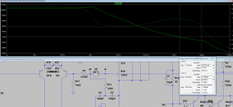
If I understand it correctly, the attached sim is done the correct way.
Shows 71.5 degree phase margin and 13.5 dB gain margin.
Shows 71.5 degree phase margin and 13.5 dB gain margin.
Attachments
Last edited:
or glue a sot23 onto the wide part of the collector/drain output pin right next to the plastic package. This point is likely to be hotter than the sink and also to respond more quickly than the sink to changes in dissipation/temperature........ drill a hole in the heat sink to fit the TO-92 transistor, wouldn't it be easier (and better) to glue the TO092 to the top surface of the power transistor ala Doug Self's thermal investigations?
Short C to B if you want to convert that monitoring sot23 to a diode.
Last edited:
the delay can be deleted, tmc_d is just the delyed output, need to settle on just one of _c, _d when you remove the delay
the phase dip is unavoidable with the higher order loop gain - you will see it with 2-pole global loop gain as well as TMC measured "inside" both loops
Ok, then the fact that the phase on the plots start at around +180 degrees instead of the ususal 0 degrees point, is due to having the TMC resistor inside the loop and it also means that you get positive gain at the 0 degrees phase point, instead of the usual -180 degrees point when you simulate CMC. Or rather, the plot shows it as +180 degrees, but in real life it is still 0 degrees?
Makes it easier and faster to get the phase margin.
Those delays you used, are they something you need to be careful of in real world applications?
Lots of questions so thanks for having the patience to answer them.
Last edited:
the delays are just one way to get an idea of what would happen if the Q you were using were slower (maybe close to saturation, under biased, worse than "typ" spec), or larger Cload (usually louspeaker cable caused) increased phase shift by reacting with output stage impedance
phase can be plotted with 360 degree ambiguity due to the software having to decide where to start "phase unwrapping" - I know people like to follow the formalism but I find a .tran will show if the loop phase is really "the wrong sign" and don't worry too much about which method uses what sign convention for AC loop gain plots
which reminds me - always start spice sim with extensive testing with .TRAN - a sim has to work in .TRAN before it is worth looking at .AC -.AC doesn't "sim" anything - no saturation, breakdown, clipping, reverse bias - it only finds the "linear" response at the operating point the DC solver finds for the circuit
Last edited:
phase can be plotted with 360 degree ambiguity due to the software having to decide where to start "phase unwrapping" - I know people like to follow the formalism but I find a .tran will show if the loop phase is really "the wrong sign" and don't worry too much about which method uses what sign convention for AC loop gain plots
So basically, if the phase starts at 0 degrees, the -180 degrees point is the positive gain point and if it starts at +180 degrees then the 0 degrees point is the positive gain point. Makes sense that the software decides where to start.
I tried repeatedly to convince bob cordel and others of this and failed.
Nice try Mike, but you are re-writing history. You still don't get it. JCX understands. TPC and TMC share many similarities, including the need to consider the whole of the feedback that the output stage "sees". However, there are also important differences between TMC and TPC. These differences, where I think your arguments were wrong, make for tradeoffs between using TPC or TMC. The designer chooses which shortcoming to live with for his own reasons. Here there is lots of room for legitimate disagreement. I happen to prefer TMC, but JCX's choice of TPC over TMC is also not unreasonable.
Cheers,
Bob
David
thanks tony
I'm sorry for asking about something that seems obvious. Which is the diode bias string? the one w/3 diodes in row or the one w/R25 in it? BTW those Zeners may be ordinary diodes....put a bias pot in series with the diode bias string.
thanks tony
David I'm sorry for asking about something that seems obvious. Which is the diode bias string? the one w/3 diodes in row or the one w/R25 in it? BTW those Zeners may be ordinary diodes.
thanks tony
Hi Tony,
Yes it's the tree diodes in a string.
But before messing with that I strongly encourage you to buy Bob's book and read it.
It will give you the means to calculate the bias currents which will get you into the ball park.
Bias is a sensitive area of a power amplifier and we don't want you to have an oops with your output transistors.
David.
Nice try Mike, but you are re-writing history. You still don't get it. JCX understands. TPC and TMC share many similarities, including the need to consider the whole of the feedback that the output stage "sees". However, there are also important differences between TMC and TPC. These differences, where I think your arguments were wrong, make for tradeoffs between using TPC or TMC. The designer chooses which shortcoming to live with for his own reasons. Here there is lots of room for legitimate disagreement. I happen to prefer TMC, but JCX's choice of TPC over TMC is also not unreasonable.
Cheers,
Bob
Actually i made all the urguments JCX is now making and you disagreed with them.
The only significant difference between TMC and TPC is that with TMC the input stage sees a single pole loop-gain roll off, while with TPC the whole amplifier sees a double pole single zero loop gain roll off.
This is why TPC is superior to TMC.
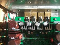
or glue a sot23 onto the wide part of the collector/drain output pin right next to the plastic package. This point is likely to be hotter than the sink and also to respond more quickly than the sink to changes in dissipation/temperature.
Short C to B if you want to convert that monitoring sot23 to a diode.
That's exactly the way I did the thermal comp in this amp proto-type. In this case the outputs are mosfets, the SOT-23 transistors are PCB mounted under the drain pins on a pad that allows me to move it about 5mm closer or further from the plastic case to adjust for best tracking. Oh yeah, and it works nicely.🙂
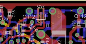
The Eagle drawing example below is from my next amp, here they are SOT-323, or SOT-23 mini, 2mm X 1.2mm. The TO-220 output device mounts horizontal to the PCB, the gate and source pins are shorter, the drain pin extends over top and contacts the SOT-323.
Attachments
In my case, I just used a drop of heat sink grease to better thermally bond the SOT transistor to the drain pin.
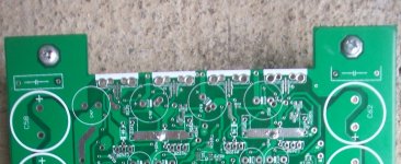
PCB
Hi there everyone,
I am bumping in again with pcb questions...
My rail voltages will be relatively high, let's say +75 and -75VDC.
Since I use a 4L board these rails will run mainly on L1 and L2. They are separated from eachother by a thin prepreg layer of 360 microns.
I suppose there will be no flashover or creepage problems but do you think there might be significant influence from one to the other and if yes, in what way this will influence quality? Distortion?
The reason for this buildup is because L3 is nearly a 100% groundplane, which should protect/shield L4 from L1 and L2. L4 contains signal earth, input and other sensible signal lines.
Since L3 (groundplane) is split into 2 : 1 island for common ground and 1 island following the contour of the board (w/o being closed !) as decoupling ground for the rails (which are on L1 & L2 partly as plane also on the contour of the board), it looks like a pitty that L2 will decouple nicely to L3 but L1 not much since L2 will be inbetween them ... should I worry about that?
Thnx guys,
Olivier
Actually i made all the urguments JCX is now making and you disagreed with them.
The only significant difference between TMC and TPC is that with TMC the input stage sees a single pole loop-gain roll off, while with TPC the whole amplifier sees a double pole single zero loop gain roll off.
This is why TPC is superior to TMC.
Mike, stop re-writing history and trying to re-argue a horse that was long ago beaten to death.
While I respect those who prefer TPC, never did I agree that TPC was better than TMC, as you wrongly assert.
I think TMC is superior. So do Baxendall, Stuart and even Self. 'Nuf said. I have no interest in re-arguing that with you. Anyone who wants to understand this better can go back to those old TMC vs TPC threads and see what was actually said. I think I also made my view clear in the chapter in my book on advanced form of feedback compensation.
Cheers,
Bob
Something administrative: somebody asked me about a PCB for Bob's Distortion Magnifier, described in Linear Audio Volume 0. Unfortunately, I lost that message and don't remember the sender's name.
If you are that person please contact me.
jan didden
If you are that person please contact me.
jan didden
- Home
- Amplifiers
- Solid State
- Bob Cordell's Power amplifier book