Borbely agrees with you. He specifies a minimum of 500mA of output bias current irrespective of how many pairs are in the output stage.Obviously, MOSFETs like more bias current, and that is a price to be paid for good MOSFET output stage linearity. This will result in the amplifier running hotter in the idle state,
He also specifies a minimum of 100mA of output bias current for each pair.
I agree as well. I demonstrated the effect of low bias over a year a go here with an HEC output follower stage comparing the difference in error between very low bias and 300mA. Big difference, but even with 300mA you can still see a Gm droop as indicated by the subtle change in slope of the error signal at the crossover.
Hi Bob
Looks like I have competition! Congratulations on coming to the end of what must have been a demanding project- I know just how much work is involved in putting together 600+ pages of hard fact.
I look forward keenly to reading it. I have my next book coming out about the end of the year- how about swopping signed copies? 🙂
The best of luck with your book- I wish it success.
Hi Bob
Looks like I have competition! Congratulations on coming to the end of what must have been a demanding project- I know just how much work is involved in putting together 600+ pages of hard fact.
I look forward keenly to reading it. I have my next book coming out about the end of the year- how about swopping signed copies? 🙂
The best of luck with your book- I wish it success.
Hi Doug,
Thanks for your kind words. I'm sure you do know how much effort is involved! Another book the end of this year? How do you do it? You are not only very prolific, but you turn out such high-quality material. I'm not sure my dear wife will ever let me write another book!
Best regards and thanks again,
Bob
MOSFET asymmetrical source resistors
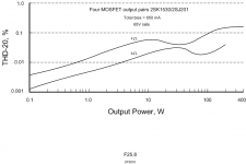
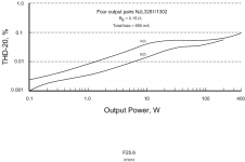
Here is some interesting data from the book regarding the THD performance achievable with class AB MOSFET output stages when asymmetrical source resistors are used to reduce relative transconductance droop and better match P-channel and N-channel transconductances. It is especially notable how the performance compares to an analogous BJT output stage with the same total bias current.
The output stage for which 20 kHz THD is shown below includes four pair of Toshiba 2SK1530/2SJ201 power MOSFETs. Each pair was biased at about 160 mA. The N-channel devices had 0.33-ohm source resistors while the P-channel devices had 0.15-ohm source resistors. The output stage was simulated using EKV models for the MOSFETs. The performance shown is the open-loop distortion of the output stage alone when driven with an ideal driver. The output stage is designed for 200 W at 8 ohms or 400 W at 4 ohms.
Cheers,
Bob
Attachments
Hi Bob
First of all congratulations with your book, if it’s written in the same wise and technical way that your posts at this forum and your emails I’m sure it’s going to be a classical “must have” for everybody that is interested in the subject “Audio amplifier design”.
Questions:
1. Do you have a plot showing the THD on the MOSFET ops, when you’re using the same source R for the N and P devices? It would be nice to compare it with the plot with different source resistors.
2. When you are using different values on the source resistors, is the reduction in the THD mostly 2H, 3H or is the reduction evenly distributed.
3. Have you done experiments with different values on the gate stopper resistors on N and P devices?
Cheers
stinius
Pre-ordered mine a week or so ago....
When the thread had just started...just now got around to posting about it.
Thank you so much for taking the time to add to the published works about audio amplifiers...
Scott
When the thread had just started...just now got around to posting about it.
Thank you so much for taking the time to add to the published works about audio amplifiers...
Scott
Preordered mine yesterday... Glad I caught the sale price, but I would have paid the full price anyway. I'm sure it's going to be well written and very interesting. Looking forward to it!
It would be even more interesting if you also tell us what kind of MOSFETs were tested. Any part numbers?
post130.
Yes, Pass' graph confirming what we often see quoted.
A mosFET stage benefits from extra bias current.
Note the 40dB reduction in distortion @ 1W as bias is increased from 62.5mA to 2A.
Yes, Pass' graph confirming what we often see quoted.
A mosFET stage benefits from extra bias current.
Note the 40dB reduction in distortion @ 1W as bias is increased from 62.5mA to 2A.
It would be even more interesting if you also tell us what kind of MOSFETs were tested. Any part numbers?
Hello
This graph come from passlabs.com in the PDF document: nelson pass-leaving_class_a
http://www.passlabs.com/pdfs/articles/leaving_class_a.pdf
A year ago I've copy text into the graph to made an image, so the image would self expain the fonction of the graph. But reading it again there is no mention of which mosfet he used.
Bye
Gaetan
Last edited:
Any part numbers?
Mr Stuart,
Nelson Pass made that graph before he started using Fairchild FQA19N20/FQA12P20 mosfets in his First Watt items.
Convenience would say he used an IRFP240/9240 output stage assembly of his XA models.
PS : forgot to thank you for the variable bias works.
That could be interpreted as cheating.
Advocating the use of Class A and vertical MOSFETs, backing it up with thd curves for different bias levels, without mentioning that the devices used are Lateral MOSFETs would imply a hoax at the least.
Credibility and scam artists do not mix.
Advocating the use of Class A and vertical MOSFETs, backing it up with thd curves for different bias levels, without mentioning that the devices used are Lateral MOSFETs would imply a hoax at the least.
Credibility and scam artists do not mix.
Hi Bob
First of all congratulations with your book, if it’s written in the same wise and technical way that your posts at this forum and your emails I’m sure it’s going to be a classical “must have” for everybody that is interested in the subject “Audio amplifier design”.
Questions:
1. Do you have a plot showing the THD on the MOSFET ops, when you’re using the same source R for the N and P devices? It would be nice to compare it with the plot with different source resistors.
2. When you are using different values on the source resistors, is the reduction in the THD mostly 2H, 3H or is the reduction evenly distributed.
3. Have you done experiments with different values on the gate stopper resistors on N and P devices?
Cheers
stinius
Hi stinius,
These are very good questions.
I've done spot checks, but no plots, for both source resistors the same, and both source resistors at 0, all with each pair biased at 165 mA. But not plots.
The biggest reduction is in 2nd harmonic, while the reductions in other harmonics are modest. For example, at 20V peak into 8 ohms, around the intermediate power THD peak, 2nd went from 0.12% down to 0.021%, when 0.33/0.15 ohms was used instead of 0.22/0.22 ohms.
3rd went down from 0.026 to 0.024, while 5th went down from 0.0065 to 0.0041. 7th actually went up from 0.0001 to 0.00024, but these numbers are very low in the first place, and only represent a single power data point.
With respect to the distortion simulations, I did it with both no gate stopper and 47 ohm gate stopper and there was essentially no difference in distortion. In amps that I have built, I have done very little experimenting with different gate stoppers. I usually use 47 ohms and a gate Zobel network with vertical MOSFETs, much as I did 25 years ago when I did my MOSFET power amp with error correction.
Hope this answers your questions,
Cheers,
Bob
It would be even more interesting if you also tell us what kind of MOSFETs were tested. Any part numbers?
Hi Edmond,
Are you referring to my data or to the data from Nelson Pass?
Mine were the Toshiba 2SK1530/2SJ201 verticals.
Cheers,
Bob
Gaetan and Jacco,
Or were it laterals? Anyhow, thanks for the response.
Cheers.
E.
Hello
I've ask Nelson Pass, the mosfets was FQA12P20 and FQA19N20C.
Bye
Gaetan
Hi Edmond,
Are you referring to my data or to the data from Nelson Pass?
Mine were the Toshiba 2SK1530/2SJ201 verticals.
Cheers,
Bob
Hi Bob,
I was referring to the data from Nelson Pass.
(I knew already that you are using 2SK1530/2SJ201 verticals 😉).
BTW, what are your favorite MOSFETs? Mine are the Toshibas, but I've also ordered a bunch of FQA12P20/FQA19N20* pairs, but not yet tested them.
Cheers,
E.
* Not the C version (FQA19N20C), which has a much higher Cgd.
PS: Thanks Gaetan.
- Home
- Amplifiers
- Solid State
- Bob Cordell's Power amplifier book