But TMC gives precisely the same total loop gain about the output stage as the equivalent TPC.
.
Perhaps a few basic sims to prove your point would be highly
appreciated.
In the waiting, a few curves ,with the relevant schematics.
Attachments
Common, Bob, for an apples and apples comparison of TMC versus TPC the component values have got to be exactly the same.
Try C1=150p; C2=300p; R1=1K for both TMC AND TPC.
For the above component values use 100ohm degeneration resistors for the input stage and 4mA tail current.
Determine the loop gain in this minor loop. You'll find it is infact a TPC response with a pole cancelling zero.
Now, plot loop gain in the other copy of your circuit with R1 connected to ground (TPC).
You should find that the total loop gain enjoyed by the output stage (and indeed the whole amp) in TPC is virtually the same as that enjoyed by the output stage alone with TMC.
Conclusion?
TMC is demonstrably inferior to TPC.
I did post my sims before reading this...
Great, the conditions are close to the ones required
in this post, although differing in the expected outcome...
True!
But TMC gives precisely the same total loop gain about the output stage as the equivalent TPC.
Infact, the TMC minor loop about the output stage (as i have demonstrated) gives a TPC loop gain response. (Try it and see for yourself.)
This suggests TMC cannot produce less distortion in an amplifier as a whole compared to the equivalent with TPC.
Hi again michael, I don't think there's anybody claiming that TMC can provide more loop gain (and therefore further distortion reduction) compared to TPC. Bob used in post #1027 a suboptimal TPC network (based on restrictive/subjective criteria for the loop gain overshoot "not more than 1dB" in his comparison, so no wonder his distortion results are in TMC favour. To me, until someone can come up with a topology that gives TMC a net advantage over TPC in terms of amp performance, TMC and TPC are, from any practical perspective, exactly equivalent.
BTW, a second order system is a second order system, that is a second order system, even if it can be approximated to a first order system. As I already mentioned in post #1079, any supposingly intelligent discussion about TMC should start by considering TMC as a second order system, unless one would like to challenge Bode's work of feedback systems.
Again, given a unity loop gain frequency, all first order systems (and in particular Miller) are providing the same amount of loop gain and hence provide the same amount of distortion reduction. Which would mean that CMC and TMC (considered as a first order system) would have to provide the same amount of distortions, which is obviously wrong. Conclusion? TMC is not a first order system. If one would want to define and promote TMC as a 1.02 order system instead of a second order system, that's fine by me, but somehow I doubt such a "definition" would catch up 🙂
Even if in simple cases (like an audio amp) TMC can be successfully approximated to a first order system, there is no guarantee that in more complex cases (like the one for compensating linear ICs, that I am after) the second order system nature of TMC won't come back and hunt you with a vengeance.
I'm relatively new on this forum, but I think the rather rude tone of the discussion here is 100% driven by overinflated egos, and cabinet skeletons dressed in old dirty laundry. Challenging is apparently not welcomed, and anybody daring such has to be executed in public, in particular if and when they make inherent mistakes. Even Baxandall and D. Self were attacked for daring to touch what appears to be the feud of a very few here. So, although there are many more open questions about, I think it's better to leave it here (that's what I'm trying to do after posting this message, hopefully it won't vanish) and move on.
Last edited:
A correctly implemented TPC amp. (i.e. one with phase lead compensation for extra phase margin and damping of the transient response) does not phase dip or overshoot either.
Prove it by showing us a complete and detailed schematic together with a simulated analysis.
edit: without solid substantiation this yes/no squabble gets really boring.
The minor loop eclosing the output stage in TMC is an outright second order system.
Oh, really?
I said already: With LT-magic [or whatever tool] you can conjure anything out of your hat. Maybe you like to fool yourself with this kind of magic, but you can't fool me.
Anyhow, below you see the Bode plot of the minor loop enclosing the output.
Should I also explain why it is an 'outright' first order system?
Attachments

Last edited:
I thought i was on your "ignore list".
Your plot is incorrect. Run the minor loop gain in this sim:
http://www.diyaudio.com/forums/soli...terview-negative-feedback-55.html#post1160809
More sims:
http://www.diyaudio.com/forums/soli...terview-negative-feedback-55.html#post1160892
Your plot is incorrect. Run the minor loop gain in this sim:
http://www.diyaudio.com/forums/soli...terview-negative-feedback-55.html#post1160809
More sims:
http://www.diyaudio.com/forums/soli...terview-negative-feedback-55.html#post1160892
Last edited:
michael's sims put the loop gain probe inside both the feedback and tmc resistors - as I suggested earlier in this thread
I hoped my last sim with the output conductance measurement would be recognized as an application of Blackman's Theorem to the same issue - but with simpiler justification than having to argue over which loop gain probe location is more "fundamental"
by ratioing the tmp, tpc conductances to the Cdom only output conductance you see a good measure of the increased loop gain with tmc, tpc - and should note their close similarity in shape
the distortion reduction, output Z reduction differences between the straight Cdom ("CMC" here?) case and both tmc, tpc are due to increased feedback, by nearly the same amount of increased feedback - an expected consequence is that tmc, tpc will show similar stability consequences of the region of 2nd order gain compared to the Cdom compensated amp
a possible test would be to incrementally increase Cload (without the decoupling series R) and watch the decrease in gain/phase margin - I predict both the tmc, tpc amps will behave (similarly) much worse than the Cdom "CMC" compensated amp - not withstanding any expectations you may have had from the "outer loop" phase/gain margin measurements
First order or Second order
The TMC minor loop is formed by the VAS gain stage with gain Av2 ( ignoring for this analysis non dominant poles and loading) and by the feedback network that is described by the admitance Y times Rin (beeing the input resistance of the Vas).
see Roberge book or Lundberg article.
By simple Kirchoff, Y = sC1(1+sRC2)/ (sR(C2+C1) +1) where C2 // R and C1<<C2. Then Y =~ SC1(1+sRC2)/(sRC2+1) = SC1
The loop transmission is AV2 Rin SC1 and the closed loop minor loop gain is 1/(sC1 Rin) for 6 to 7 decades. The first order system is coming from the fact that the pole and the zero are cancelling each other in the admittance formula.
JPV
Common, Bob, for an apples and apples comparison of TMC versus TPC the component values have got to be exactly the same.
Try C1=150p; C2=300p; R1=1K for both TMC AND TPC.
For the above component values use 100ohm degeneration resistors for the input stage and 4mA tail current.
Note, place 47p in series with 1k for phase lead compensation across the feedback resistor which should be 10K. The other feedback resistor connected to ground and the diff. stage should be 510ohms.
When you're done comparing THD, generate an extra copy of the circuit and use the loop gain probe on the TMC version; begin by placing the probe between the output of the amp and R1.
Determine the loop gain in this minor loop. You'll find it is infact a TPC response with a pole cancelling zero.
This suggests that, for a start, to ensure stability of this minor loop, resistor R1 must be selected to locate this essential zero well before the minor loops unity gain frequency.
Now, plot loop gain in the other copy of your circuit with R1 connected to ground (TPC).
You should find that the total loop gain enjoyed by the output stage (and indeed the whole amp) in TPC is virtually the same as that enjoyed by the output stage alone with TMC.
Conclusion?
TMC is demonstrably inferior to TPC.
Mike,
I disagree that the component values must be the same for apples-apples, and I also don't like phase lead compensation in the feedback path. You should not be using that as a crutch to make TPC look better. There is absolutely nothing wrong with the TMC design I chose - it yields exceptional performance and stability. Now, as I have already said, I may not have optimized the TPC part.
Do you agree with that statement? If so, and without phase lead compensatiom, and with the same global feedback gain crossover frequency, tell me what TPC values you would like me to put in and I'll do the comparison.
The proof is in the pudding - it is not in waiving one's hands about how much loop gain must enclose what stage.
Cheers,
Bob
I thought i was on your "ignore list".
You are still on my ignore lists. But sometimes my curiosity prevailed over my principle and I couldn't resist the temptation to prove that your bold statements don't hold water.
Your plot is incorrect. Run the minor loop gain in this sim:
http://www.diyaudio.com/forums/soli...terview-negative-feedback-55.html#post1160809
Nothing wrong with my plot, instead, the definition of 'The minor loop enclosing the output stage' is wrong. To me 'minor' means small and/or locally. So I understood you meant the local loop around the OPS and TMC resistor and nothing else. Now it appeared that the branch to the global NFB loop should be included. No one would call that a 'minor loop'.
May I ask you which 'genius' has invented this highly confusing terminology?
apples-apples
Hi Bob,
Indeed, that is a ridiculous requirement for a fair apples to apples comparison. The only things that matter are global properties like frequency/phase/step responses, bandwidth, phase margin, phase dispersion, stability, sensitivity to reactive loads, recovery from overload conditions, etc.
Cheers,
E.
Mike,
I disagree that the component values must be the same for apples-apples...........
Cheers,
Bob
Hi Bob,
Indeed, that is a ridiculous requirement for a fair apples to apples comparison. The only things that matter are global properties like frequency/phase/step responses, bandwidth, phase margin, phase dispersion, stability, sensitivity to reactive loads, recovery from overload conditions, etc.
Cheers,
E.
magic or how to fool yourself
Hi jcx,
Thanks for the hint and clarifying the confusion.
Nevertheless I must repeat my phrase: With LT-magic you can conjure anything out of your hat. You can put a gain probe anywhere, but that doesn't always mean the results make sense, let alone you can determine the order of the system in question based on those results.
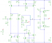
Let's take for example a simple line-amp, comprising a LTP, an I-mirror and VAS, followed by a high speed output buffer. The Miller compensation includes the output. (yes it's rock stable: the phase margin of the local Miller loop is 85 degrees)
I hope that everyone will agree that, opposed to TPC, such an arrangement is basically first order system. Okay?
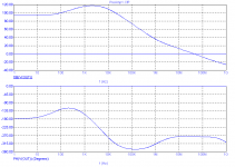
Now, let's look at the response of the so called 'minor loop including the OPS', by injecting the signal into the Miller cap (in order to include the OPS) as well into the NFB resistor (in order to comply with the weird definition of 'minor'). See fig. 1
Holy cow! WTF is this? An enormous phase dip and a roll-off at 100kHz of ~40dB/decade (fig. 2). Well, I'm blowed! Surely, that must be a second order system.
Bottom line: one must be very careful where to put the gain probe and how to interpret the results. If done mindlessly, it easily leads to wrong conclusions.
Cheers,
E.
PS: Of course I could have used a more sophisticated Middlebrook or Tia gain probe, but I safely bet that you will get similar results.
michael's sims put the loop gain probe inside both the feedback and tmc resistors - as I suggested earlier in this thread
[snip]
Hi jcx,
Thanks for the hint and clarifying the confusion.
Nevertheless I must repeat my phrase: With LT-magic you can conjure anything out of your hat. You can put a gain probe anywhere, but that doesn't always mean the results make sense, let alone you can determine the order of the system in question based on those results.
Let's take for example a simple line-amp, comprising a LTP, an I-mirror and VAS, followed by a high speed output buffer. The Miller compensation includes the output. (yes it's rock stable: the phase margin of the local Miller loop is 85 degrees)
I hope that everyone will agree that, opposed to TPC, such an arrangement is basically first order system. Okay?
Now, let's look at the response of the so called 'minor loop including the OPS', by injecting the signal into the Miller cap (in order to include the OPS) as well into the NFB resistor (in order to comply with the weird definition of 'minor'). See fig. 1
Holy cow! WTF is this?
An enormous phase dip and a roll-off at 100kHz of ~40dB/decade (fig. 2). Well, I'm blowed! Surely, that must be a second order system.Bottom line: one must be very careful where to put the gain probe and how to interpret the results. If done mindlessly, it easily leads to wrong conclusions.
Cheers,
E.
PS: Of course I could have used a more sophisticated Middlebrook or Tia gain probe, but I safely bet that you will get similar results.
Attachments
Mike,
I disagree that the component values must be the same for apples-apples, and I also don't like phase lead compensation in the feedback path.
Then we'll have to agree to disagree.
Utter nonsense.Hi Bob,
Indeed, that is a ridiculous requirement for a fair apples to apples comparison. The only things that matter are global properties like frequency/phase/step responses, bandwidth, phase margin, phase dispersion, stability, sensitivity to reactive loads, recovery from overload conditions, etc.
Cheers,
E.
2nd order gain is the reason for the Cdom compensation:
http://web.mit.edu/klund/www/papers/ACC04_opcomp.pdf
we do tend to look for cut points, tests that serve the purpose we are interested in - not all are easily interpeted nor individually give a complete picture (that's why I had some hope for the output conductance measurement, particularly ratioing the output conductance of identical circuits when the only variable is a change in feedback connection; CMC vs TPC, TMC)
compared to his recent posts this exchange:
and yes I do think HEC is usefully examined by cutting the inner loop and looking at the total gain applied around the output Q:
http://web.mit.edu/klund/www/papers/ACC04_opcomp.pdf
we do tend to look for cut points, tests that serve the purpose we are interested in - not all are easily interpeted nor individually give a complete picture (that's why I had some hope for the output conductance measurement, particularly ratioing the output conductance of identical circuits when the only variable is a change in feedback connection; CMC vs TPC, TMC)
compared to his recent posts this exchange:
I certainly call that one arbitrary - with nested loop structures like your feedback EC or others recently mentioned: TMC, OMC, NDFL the outer global feedback loop T doesn't necessarily predict stability properties
This is clearly true of your amp in my sim (previous page), the gain intercept with both output stage enclosing feedback loops cut gives feedback gain 0 dB intercept frequency of 4.3 MHz and 78 dgrees phase margin
leads me to ask whether Bob has been abducted by Aliens - Bring back the Real Bob CordellI agree completely; the global feedback gain crossover is only one parameter to keep an eye on. Those inner loops in any of the techniques can really get you, and must be watched closely.
However, I think it is still useful to have a common global NFB loop gain crossover for the apples-apples comparisons. Else the guy who pushes it to 2 MHz might get a 6 dB advantage without proving much about the underlying differences among the techniques we are trying to evaluate.
Cheers,
Bob
and yes I do think HEC is usefully examined by cutting the inner loop and looking at the total gain applied around the output Q:
...I rolled together an "improved" version of my smplCherryMosfetAmp sim and my CordellMosfetAmp sim
I've plotted "loop gain" as measured by the tain/middlebrook methods - see your swcadiii/examples/educational/loopgain2.asc
also I show the simple series Vsource and full "loop gain" curves for the Cordell EC amp because there is an interesting difference that needs explaining - but I don't have the explaination yet - and the simple method gives a curve that meets my understanding of what the EC circuit is doing to output stage distortion
both methods agree at the gain intercept so I'm pretty confident that the stability is properly represented by these curves
Green is smplCherry NDFL sim, left circuit
Red/Yellow my CordellMosfetAmp sim with 2 "loop gain" mesurement methods
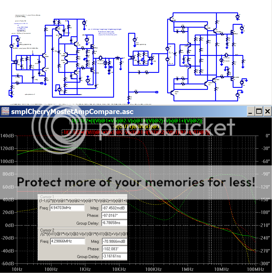
cursor 1: smplCherry gain intercept
cursor 2: Cordell EC gin intercept
The smplCherry NDFL is quite similar in high frequency stability to my Cordell EC sim - but the Cherry loop gain increases more aggressively at lower frequencies than the Cordell amp sim, indicating a greater propensity for Large signal instability/bad clipping performance as a trade for greater gain at high audio frequencies that brings down Bob's thd20
I claim the similar distortion reduction results are directly related to the gain around the output Mosfets
I presently suspect the minor positive feedback loop inherent in the EC scheme of complicating the Tain loop gain calculation, I'm currently looking for a clear explaination of measuring T and calculating desensitivity with (unstable) minor loops inside stable negative feedback amplifiers - any pointers?
Last edited:
Of course, everything that might reveal that your beloved baby is a horrible kludge, is nothing but 'utter nonsense'.Utter nonsense.
BTW, thank you for your compliment. G'day mate!
minor loop and some definitions
The compensation techniques of feedback systems are split in two classes: series compensation and feedback compensation.
Series compensation modifies the DC gain or dynamic of one or more elements in the main loop beeing a forward or a feedback element. Lead and Lag compensation are part of this class.
Feedback compensation is implemented by adding a feedback element which creates a two loop system. The inner loop is called the minor loop, the main one is called the major loop.
The objective of both compensation techniques is to maintain the ideal closed loop transfer function with acceptable dynamic performance.
The minor loop technique is very versatile and powerfull to modify the dynamic of a feedback system. Miller, Nested Miller, two pole compensation, TMC are minor loop techniques.
JPV
JPV
Thanks Jean-Pierre,
Still, I'm a bit confused. Regarding a 'blameless amp' for example, is the Miller loop the so called 'minor loop' and the global negative feedback loop the 'major loop'?
Cheers,
E.
Still, I'm a bit confused. Regarding a 'blameless amp' for example, is the Miller loop the so called 'minor loop' and the global negative feedback loop the 'major loop'?
Cheers,
E.
Thanks Jean-Pierre,
Still, I'm a bit confused. Regarding a 'blameless amp' for example, is the Miller loop the so called 'minor loop' and the global negative feedback loop the 'major loop'?
Cheers,
E.
Yes exactly
JPV
Yes exactly
JPV
Thanks! Now, referring to post 1125, we can safely discard Mike's comments as 'utter nonsense' (his language, not mine).
Cheers,
E.
- Home
- Amplifiers
- Solid State
- Bob Cordell's Power amplifier book