To be precise TMC generates virtually the same total loop gain about the output stage as the equivalent TPC network.
Indeed, TMC applies the TPC loop gain characteristic about the output stage alone while TPC provides the same double-pole loop gain characteristic for the WHOLE amplifier.
TPC is therefore vastly superior to TMC.
Hi Mike,
There has been a lot of discussion and disagreement here about how TPC and TMC work, what the differences are, and which is a more effective compensation technique.
Based on the full-amplifier simulation results I presented in Post 1027, I believe that TMC is superior in a typical practical amplifier. What say you to these specific simulation results?
Cheers,
Bob
Actually , what counts is the end result. TMC SOUNDS better than no TMC (same amp) , which ultimately validates it . No safety issues, either. I have thoroughly abused a TMC enabled amp and have no "burning amp" . 🙂
Not just superior theoretically , but easy and safe real world results are to be expected. I have moved beyond "belief" , I KNOW.
OS
YWN,
in my view, you are the only one here who has made relevant observations and conclusions. I´m impressed.
in my view, you are the only one here who has made relevant observations and conclusions. I´m impressed.
Moreover,
the benefit of extended bandwidth needs to be weighed against stability level, response time and distortions induced in other ways. A comparison is not simple. Anyway, the sum of distortions will depend on the time delay magnitude, all you can do is choose between different distortions.
In practice, pole-zero cancellation is not possible, also not even a precise pole-zero cancellation would result in stability and the complicated calculations involved have limited validity in the field.
I would not implement two-pole compensation in dynamic systems like a typical power amplifier with feedback and again, I strongly reject all the diffuse assertions about distortion reduction, for which there´s no theoretical bases whatsoever.
Heaving a deep and troubled sigh, the transcendental pole-zero cancellation guru further said: Behold, you never stop being amazed by how wishful thinkers steadfastly try to fool physics, but always end up with fooling themselves. Then he straightened his pagri and left humbly.Therefore TMC behaves like a 1st order system. period
Hat
Nice try, jcx.
With LT-magic you can conjure anything out of your hat. Maybe you like to fool yourself with this kind of magic, but you can't fool me.
Anyhow, the question was whether The 2nd order terms of TMC are so small that we safely can ignore them and, consequently, we may consider TMC a 1st order system.
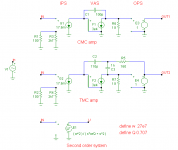
To get an answer, I've simmed two fairly standard amps with a conventional Miller compensation (CMC) and TMC. For comparison I have also simmed a 2nd order Laplace function.
To exclude minor side effects from real components, I've used synthetic ones instead: a VCCS (for the IPS), a CCCS (for the VAS) and a VCVS (for the OPS). See 1st pic. The ULGF and transition frequency are both 1MHz and the closed loop gain is 28x, though the global NFB has been disabled (by connecting R3 and R4 to ground) in order to investigate the open loop responses, See 2nd pic.
As expected, the Bode plot of the CMC amp rolls off steadily with 20dB/decade and the phase is a constant -90 degrees. See the blue curves (as far as visible).
Now, let's look at the Bode plot of the TMC amp, the green curves. These curves coincidence with the CMC curves. For the unbelievers I've also plot the difference of them, see the black curve (0dB).
Finally, have a look at the response of a critically damped 2nd order thingy (red curves). Clearly they are totally different. Beyond Wo: 40dB/decade roll-off and a phase shift up to -180 degrees.
Bottom line: TMC is essentially a first order system.
Cheers,
E.
[snip]
its really hard to see why anyone would want to get hung up on the semantics - if you want to call the TMC output step response "almost 1st order" I suppose you could - but I can tell the difference by eyeball in this sim and no ther aspect of TMC can be profitably talked about as a "1st order" system
Nice try, jcx.
With LT-magic you can conjure anything out of your hat. Maybe you like to fool yourself with this kind of magic, but you can't fool me.
Anyhow, the question was whether The 2nd order terms of TMC are so small that we safely can ignore them and, consequently, we may consider TMC a 1st order system.
To get an answer, I've simmed two fairly standard amps with a conventional Miller compensation (CMC) and TMC. For comparison I have also simmed a 2nd order Laplace function.
To exclude minor side effects from real components, I've used synthetic ones instead: a VCCS (for the IPS), a CCCS (for the VAS) and a VCVS (for the OPS). See 1st pic. The ULGF and transition frequency are both 1MHz and the closed loop gain is 28x, though the global NFB has been disabled (by connecting R3 and R4 to ground) in order to investigate the open loop responses, See 2nd pic.
As expected, the Bode plot of the CMC amp rolls off steadily with 20dB/decade and the phase is a constant -90 degrees. See the blue curves (as far as visible).
Now, let's look at the Bode plot of the TMC amp, the green curves. These curves coincidence with the CMC curves. For the unbelievers I've also plot the difference of them, see the black curve (0dB).
Finally, have a look at the response of a critically damped 2nd order thingy (red curves). Clearly they are totally different. Beyond Wo: 40dB/decade roll-off and a phase shift up to -180 degrees.
Bottom line: TMC is essentially a first order system.
Cheers,
E.
Attachments

Thanks Edmond.
You are one of the few who provide evidence for your peers to pore over.
Some day we may get agreement when the doubters finally start reading and understanding the evidence.
For the time being, I am just a watcher.
You are one of the few who provide evidence for your peers to pore over.
Some day we may get agreement when the doubters finally start reading and understanding the evidence.
For the time being, I am just a watcher.
Nice try, jcx.
With LT-magic you can conjure anything out of your hat. Maybe you like to fool yourself with this kind of magic, but you can't fool me.
Anyhow, the question was whether The 2nd order terms of TMC are so small that we safely can ignore them and, consequently, we may consider TMC a 1st order system.
To get an answer, I've simmed two fairly standard amps with a conventional Miller compensation (CMC) and TMC. For comparison I have also simmed a 2nd order Laplace function.
To exclude minor side effects from real components, I've used synthetic ones instead: a VCCS (for the IPS), a CCCS (for the VAS) and a VCVS (for the OPS). See 1st pic. The ULGF and transition frequency are both 1MHz and the closed loop gain is 28x, though the global NFB has been disabled (by connecting R3 and R4 to ground) in order to investigate the open loop responses, See 2nd pic.
As expected, the Bode plot of the CMC amp rolls off steadily with 20dB/decade and the phase is a constant -90 degrees. See the blue curves (as far as visible).
Now, let's look at the Bode plot of the TMC amp, the green curves. These curves coincidence with the CMC curves. For the unbelievers I've also plot the difference of them, see the black curve (0dB).
Finally, have a look at the response of a critically damped 2nd order thingy (red curves). Clearly they are totally different. Beyond Wo: 40dB/decade roll-off and a phase shift up to -180 degrees.
Bottom line: TMC is essentially a first order system.
Cheers,
E.
The CMC should have (with the values you are giving) a GBW ( or ULG or frequency where the loop gain is one) of gm1/2piC = 28 Mhz providing the other poles are at higher frequency ( what you assumed).
If we look at the TMC minor loop, its closed loop gain is 1/YR1 where Y is the admittance of the TMC feedback network and R1 is the input resistance of the VAS// with the output resistance of the first stage. This is for frequencies where the TMC loop gain is high >>1.
With the values given ( C2>>C1) Y~=sC1 and the TMC stage is an integrator down to the point where the TMC loop gain is <<1. There the TMC stage gain becomes constant ( = DC gain of the VAS).
So TMC and CMC behave as integrator down to low frequencies where they should have both the DC gain ( this I do not see in you simulation).
Except these two questions ( GBW of CMC and DC gain of TMC) it is obvious that TMC or CMC compensated two stage amplifier behaves like a first order system for the frequencies of interest.
Do you agree Edmond
JPV
Nice try, jcx.
With LT-magic you can conjure anything out of your hat. Maybe you like to fool yourself with this kind of magic, but you can't fool me.
Anyhow, the question was whether The 2nd order terms of TMC are so small that we safely can ignore them and, consequently, we may consider TMC a 1st order system.
To get an answer, I've simmed two fairly standard amps with a conventional Miller compensation (CMC) and TMC. For comparison I have also simmed a 2nd order Laplace function.
To exclude minor side effects from real components, I've used synthetic ones instead: a VCCS (for the IPS), a CCCS (for the VAS) and a VCVS (for the OPS). See 1st pic. The ULGF and transition frequency are both 1MHz and the closed loop gain is 28x, though the global NFB has been disabled (by connecting R3 and R4 to ground) in order to investigate the open loop responses, See 2nd pic.
As expected, the Bode plot of the CMC amp rolls off steadily with 20dB/decade and the phase is a constant -90 degrees. See the blue curves (as far as visible).
Now, let's look at the Bode plot of the TMC amp, the green curves. These curves coincidence with the CMC curves. For the unbelievers I've also plot the difference of them, see the black curve (0dB).
Finally, have a look at the response of a critically damped 2nd order thingy (red curves). Clearly they are totally different. Beyond Wo: 40dB/decade roll-off and a phase shift up to -180 degrees.
Bottom line: TMC is essentially a first order system.
Cheers,
E.
Nice work, Edmond. I agree with what you have done and concluded here, with an ever-so-slight caveat. As I had mentioned in an earlier post, when an output stage has gain less than unity, the TMC may take on some very minor attributes of a second-order system. You might try your idealized TMC simulation with an output stage gain of 0.9 and see what you get. Nevertheless, you have properly qualified your assertion by saying that the departures of TMC from a true first order system in practice in a reasonable application are negligible.
For all practical purposes, TMC acts as a first order system and to quibble about very fine distinctions in semantics is unnecessary and detracts from understanding of the differences between TPC and TMC.
The similarity of appearance of the TPC and TMC schematics has enticed some into thinking that TPC and TMC are largely the same, and this is simply not the case. Moreover, I think that some here, having been so enticed, have used the same values for the C's and R for both TPC and TMC. This gives misleading results. If one uses the same R for TMC as for TPC (capacitors being the same), one gets extremely sub-optimal TMC in my opinion. In general, the R in TMC wants to be substantially lower than the R in TPC. This is the way I did it in the simulation example above where I showed that in a simulated real amplifier TMC was superior.
As discussed earlier, I do agree that the agressiveness of TPC used is a matter of choice, and TPC can be made to perform with larger distortion reduction than I showed if it is made more agressive, but in my opinion that involves added risk.
It is also true that TMC does nothing for improving the life of the input stage compared to conventional Miller compensation, while TPC does act to reduce distortion introduced by the input stage. Yes, it is certainly true that the increased global feedback afforded by TPC helps all parts of the amplifier. But TMC specifically and effectively attacts the most insidiuos contributor to distortion, namely the output stage.
Cheers,
Bob
The CMC should have (with the values you are giving) a GBW ( or ULG or frequency where the loop gain is one) of gm1/2piC = 28 Mhz providing the other poles are at higher frequency ( what you assumed).
Hi Jean-Pierre,
That's right, ~28MHz for CMC as well for TMC.
If we look at the TMC minor loop, its closed loop gain is 1/YR1 where Y is the admittance of the TMC feedback network and R1 is the input resistance of the VAS// with the output resistance of the first stage. This is for frequencies where the TMC loop gain is high >>1.
With the values given ( C2>>C1) Y~=sC1 and the TMC stage is an integrator down to the point where the TMC loop gain is <<1. There the TMC stage gain becomes constant ( = DC gain of the VAS).
So TMC and CMC behave as integrator down to low frequencies where they should have both the DC gain (this I do not see in you simulation).
Due to the use of idealized components, the frequency where the gain flattens and becomes equal to the DC gain, is extreme and unrealistic low: about 1 micro Hz (far beyond the used scale). That's why you can't see it in the plots.
Except these two questions ( GBW of CMC and DC gain of TMC) it is obvious that TMC or CMC compensated two stage amplifier behaves like a first order system for the frequencies of interest.
Do you agree Edmond
JPV
I fully agree with that.
Cheers,
E.
Edmond,
I must have misread your graph.
To me TMC and CMC loop must have the same DC loop gain, therefore my question because you are showing TMC vs CMC as different at low frequencies.
JPV
I must have misread your graph.
To me TMC and CMC loop must have the same DC loop gain, therefore my question because you are showing TMC vs CMC as different at low frequencies.
JPV
The order of TMC
Hi Bob,
I agree with all your points.
>You might try your idealized TMC simulation with an output stage gain of 0.9
Actually, I did already that (with a non-idealized amp). More precisely, I tied the TMC resistor to the wiper of pot and the other two legs (of the pot) to the output respectively to ground. With this setup you can gradually change from TMC to TPC. What you see is that the distortion stays about the same, but the more you turn the wiper to ground, the more overshoot you get (edit: and the more it becomes a 2nd order system).
In case of a BJT OPS, the gain is about 0.98. Therefore, as pointed out here: http://www.diyaudio.com/forums/soli...erview-negative-feedback-326.html#post2382015 the order is 1.02, so to speak. But, admittedly, you said it more eloquently: TMC may take on some very minor attributes of a second-order system.
As you see, also on this point we fully agree with each other.
Cheers,
E.
Nice work, Edmond. I agree with what you have done and concluded here, with an ever-so-slight caveat. As I had mentioned in an earlier post, when an output stage has gain less than unity, the TMC may take on some very minor attributes of a second-order system. You might try your idealized TMC simulation with an output stage gain of 0.9 and see what you get. Nevertheless, you have properly qualified your assertion by saying that the departures of TMC from a true first order system in practice in a reasonable application are negligible.
For all practical purposes, TMC acts as a first order system and to quibble about very fine distinctions in semantics is unnecessary and detracts from understanding of the differences between TPC and TMC.
The similarity of appearance of the TPC and TMC schematics has enticed some into thinking that TPC and TMC are largely the same, and this is simply not the case. Moreover, I think that some here, having been so enticed, have used the same values for the C's and R for both TPC and TMC. This gives misleading results. If one uses the same R for TMC as for TPC (capacitors being the same), one gets extremely sub-optimal TMC in my opinion. In general, the R in TMC wants to be substantially lower than the R in TPC. This is the way I did it in the simulation example above where I showed that in a simulated real amplifier TMC was superior.
As discussed earlier, I do agree that the agressiveness of TPC used is a matter of choice, and TPC can be made to perform with larger distortion reduction than I showed if it is made more agressive, but in my opinion that involves added risk.
It is also true that TMC does nothing for improving the life of the input stage compared to conventional Miller compensation, while TPC does act to reduce distortion introduced by the input stage. Yes, it is certainly true that the increased global feedback afforded by TPC helps all parts of the amplifier. But TMC specifically and effectively attacts the most insidiuos contributor to distortion, namely the output stage.
Cheers,
Bob
Hi Bob,
I agree with all your points.
>You might try your idealized TMC simulation with an output stage gain of 0.9
Actually, I did already that (with a non-idealized amp). More precisely, I tied the TMC resistor to the wiper of pot and the other two legs (of the pot) to the output respectively to ground. With this setup you can gradually change from TMC to TPC. What you see is that the distortion stays about the same, but the more you turn the wiper to ground, the more overshoot you get (edit: and the more it becomes a 2nd order system).
In case of a BJT OPS, the gain is about 0.98. Therefore, as pointed out here: http://www.diyaudio.com/forums/soli...erview-negative-feedback-326.html#post2382015 the order is 1.02, so to speak. But, admittedly, you said it more eloquently: TMC may take on some very minor attributes of a second-order system.
As you see, also on this point we fully agree with each other.
Cheers,
E.
Last edited:
Edmond,
I must have misread your graph.
To me TMC and CMC loop must have the same DC loop gain, therefore my question because you are showing TMC vs CMC as different at low frequencies.
JPV
Hi Jean-Pierre,
Of course the DC gain of the TMC vs the CMC version is the same.
Perhaps the term 'difference' was a bit misleading. My apologies.
I meant the difference in gain in terms of decibels.
The black curve represents: dB(v(out1)/v(out2)) = dB(v(out1) - dB(v(out2)) = 0
Cheers,
E.
</p>
Hi michael, I was talking about the loop gain phase, that always dips for an effective TPC compensation. Correspondingly, the closed loop TPC compensated amp always overshoots.
A correctly implemented TMC does not phase dip and overshoot in the closed loop.
A correctly implemented TPC amp. (i.e. one with phase lead compensation for extra phase margin and damping of the transient response) does not phase dip or overshoot either.
It is also true that TMC does nothing for improving the life of the input stage compared to conventional Miller compensation, while TPC does act to reduce distortion introduced by the input stage. Yes, it is certainly true that the increased global feedback afforded by TPC helps all parts of the amplifier.
True!
But TMC specifically and effectively attacts the most insidiuos contributor to distortion, namely the output stage.
But TMC gives precisely the same total loop gain about the output stage as the equivalent TPC.
Infact, the TMC minor loop about the output stage (as i have demonstrated) gives a TPC loop gain response. (Try it and see for yourself.)
This suggests TMC cannot produce less distortion in an amplifier as a whole compared to the equivalent with TPC.
I’ve run some amplifier simulations to try to arrive at apples-apples comparisons of straight Miller compensation, TPC and TMC. This should shed some light on the speculation about the performance of TPC vs. TMC in particular. The same fairly simple amplifier was simulated with the three different forms of compensation. My definition of apples-apples was that the gain crossover frequency of all three approaches was the same (1 MHz), that peaking of more than 1 dB was not allowed, and that all three arrangements had about the same amount of stability (good). Performance was evaluated with a 4-ohm load.
The amplifier simulated is a simple, medium-performance design similar to Figure 3.10 in my book. It uses a BJT input LTP with a tail current of 1mA, degenerated with 470 ohm resistors, and loaded with a two-transistor current mirror. The design uses a single-ended Darlington VAS loaded with a 10mA current source. The output stage is a Locanthi Triple with a single output pair of MJL21193/21194 transistors biased at 115 mA with RE=0.22 ohms.
Closed loop gain was set to 20 with a feedback network consisting of 3800 ohms and 200 ohms. Open-loop gain was inferred by setting closed loop gain to 50,000 by increasing the feedback resistor to 10 Meg with output DC offset trimmed to <10mV.
All versions had a gain crossover frequency of 1 MHz when driving a 4-ohm load. Closed loop gain and stability was checked with an additional shunt load of 1.0 ohm and 0.01 uF in series. This loading arrangement was also in place when compensation was designed. No output L-R network was used.
For purposes of discussion, the compensating capacitor that connects to the input of the VAS is designated as C1. The resistor forming the “T” with C1 and C2, if used, is designated as R1.
TPC was designed by making C1 and C2 equal in value and adjusting R1 downward in value until closed-loop gain peaking was 1 dB (300 kHz). The value of C1 and C2 was set to achieve a gain crossover frequency of 1 MHz. Square wave overshoot with TPC was 20%. The TPC design had 53 dB of loop gain at 20 kHz.
TMC was designed by making C2 five times C1. R1 was then adjusted downward until the closed-loop frequency response above the gain crossover frequency began to show signs of slightly diminished roll-off rate. C1 and C2 were set to achieve a gain crossover frequency of 1 MHz. The TMC and Miller designs had about 34 dB of loop gain at 20 kHz and exhibited no peaking or overshoot. Important performance comparisons are as follows:
THD-20:
Miller: 0.015 %
TPC: 0.007 %
TMC: 0.002 %
7th Harmonic:
Miller: 15 ppm
TPC: 11 ppm
TMC: 3 ppm
Slew Rate:
Miller: 50 V/us
TPC: 73 V/us
TMC: 52 V/us
In this apples-apples comparison TMC was superior to TPC in every regard except slew rate. As expected, slew rate for TPC was higher by about 40%. TMC provided a full 7:1 improvement in THD-20 over straight Miller compensation and a 5:1 improvement in 7th harmonic content.
TPC actually provided disappointing improvements over straight Miller compensation, and I make no claim that there are not more optimized versions of TPC that could have been used. Bear in mind my constraint of no more than 1 dB of peaking. It is possible that TPC wherein C1 and C2 are not equal may perform better while still obeying the 1 dB cap on peaking.
TPC provided only a 2:1 improvement in THD-20 over straight Miller compensation and only a 27% reduction in 7th harmonic content. How can this be, given that TPC has fully 19 dB more feedback at 20 kHz? The harmonics of interest don’t lie at 20 kHz; they lie at 60 kHz and above. By its very nature, TPC loop gain falls faster than 6 dB/octave in the ultrasonic range. At 60 kHz, TPC has only 8 dB more feedback than straight Miller compensation.
The attached Word document summarizes the results.
It is notable that TPC may do relatively better in 19+20kHz CCIF IM performance because in that test the IM products lie at frequencies where TPC provides more loop gain. I have not verified that with simulation, however.
Cheers,
Bob
Common, Bob, for an apples and apples comparison of TMC versus TPC the component values have got to be exactly the same.
Try C1=150p; C2=300p; R1=1K for both TMC AND TPC.
For the above component values use 100ohm degeneration resistors for the input stage and 4mA tail current.
Note, place 47p in series with 1k for phase lead compensation across the feedback resistor which should be 10K. The other feedback resistor connected to ground and the diff. stage should be 510ohms.
When you're done comparing THD, generate an extra copy of the circuit and use the loop gain probe on the TMC version; begin by placing the probe between the output of the amp and R1.
Determine the loop gain in this minor loop. You'll find it is infact a TPC response with a pole cancelling zero.
This suggests that, for a start, to ensure stability of this minor loop, resistor R1 must be selected to locate this essential zero well before the minor loops unity gain frequency.
Now, plot loop gain in the other copy of your circuit with R1 connected to ground (TPC).
You should find that the total loop gain enjoyed by the output stage (and indeed the whole amp) in TPC is virtually the same as that enjoyed by the output stage alone with TMC.
Conclusion?
TMC is demonstrably inferior to TPC.
Last edited:
A correctly implemented TPC amp. (i.e. one with phase lead compensation for extra phase margin and damping of the transient response) does not phase dip or overshoot either.
Hi michael, maybe, but then the lead phase adds more variables to the discussion.
Otherwise, in my opinion, the phase dip and the overshoot are irrelevant for audio. This is something that can easily be addressed in the input filter (which is anyway mandatory, I guess that's what you mean by "damping"), to get a near ideal exponential step response with an appropriate time constant.
Provided that the amp is unconditionally stable (that is, the phase never dips under 180 degrees before the unity loop gain frequency is reached, so the amp is stable for all closed loop gains) I am not sure why Bob feels "nervous" about and what is the "added risk".
The order of TMC
Hi Bob,
I did just that. Even to my own surprise, it appears that the magnitude, respectively phase curves still coincidence very closely. IOW, also with a OPS gain of 0.9, TMC is hardly to distinguish from a first order system. The max. magnitude deviation (peak to peak and in given frequency range) is 0.0087dB and the max. phase deviation is 0.029 degrees.
No one would call this a second order system (except syn09, of course).
Cheers,
E.
..................
You might try your idealized TMC simulation with an output stage gain of 0.9 and see what you get.
.................
Cheers,
Bob
Hi Bob,
I did just that. Even to my own surprise, it appears that the magnitude, respectively phase curves still coincidence very closely. IOW, also with a OPS gain of 0.9, TMC is hardly to distinguish from a first order system. The max. magnitude deviation (peak to peak and in given frequency range) is 0.0087dB and the max. phase deviation is 0.029 degrees.
No one would call this a second order system (except syn09, of course).
Cheers,
E.
- Home
- Amplifiers
- Solid State
- Bob Cordell's Power amplifier book