I don't think you can go 60V rail
That's indeed apparent in several low Re value designs, many more output device pairs than required for the output level, and rails <60Vdc.
(and a Vbe spreader with more than one tempco compensating device, of the same gender and in series)
That's indeed apparent in several low Re value designs, many more output device pairs than required for the output level, and rails <60Vdc.
(and a Vbe spreader with more than one tempco compensating device, of the same gender and in series)
Jacco, there's another more pressing reason I think.
If you look at the device SOA for rails of 60V and above, you need multiple pairs just for secondary breakdown safety with reactive loads, and not for dissipation related stuff.
With reactive loads your output devices may be called upon to withstand the full supply voltage (in this case > 100V) while sourcing appreciable current. Even nominally 250 W devices can often only do 1A, tops, at Vce 100V for a short time.
jan
All the talk of Class-A output and crossover distortion makes me want to ask this question. Is it really that great a problem in actual listening tests when an amplifier goes through that narrow band of change from Class-A to Class-B operation? If you could idle the amplifier at the highest crossover distortion point on purpose would it sound terrible or is this just a red herring that audiophiles have bought into? Perhaps it is that bad, I don't know, I have never noticed some very abrupt bad area and then a good area as it goes from one class to the other with a musical signal. Perhaps with sine waves it would be noticeable, but with dynamic musical signal is this all overblown?
Jacco, there's another more pressing reason I think.
If you look at the device SOA for rails of 60V and above, you need multiple pairs just for secondary breakdown safety with reactive loads, and not for dissipation related stuff.
With reactive loads your output devices may be called upon to withstand the full supply voltage (in this case > 100V) while sourcing appreciable current. Even nominally 250 W devices can often only do 1A, tops, at Vce 100V for a short time.
jan
The NJL3281 can do 1A at 100V for 1 second. It can do 2A at 100V for 50ms (half of a 10Hz sinusoid). I'm assuming that the graph in the spec sheet assumes a starting junction temperature of 25C.
This assumes a peak junction temperature of 150C. The above numbers must be de-rated if the junction is nominally starting at, say 50C.
On the test bench at 1/3 power, this would be a rather significant exacerbation of the SOA matter.
In the real world with music of a decent crest factor, the problem would be less. However, in the real world with music that is highly compressed and having a low crest factor, and being played at high volume, this SOA matter can once again be exacerbated.
Cheers,
Bob
(I was referring to output stage designs of the likes of 6 pairs of 200W devices, and a Pd/P ratio of 20)
If you could idle the amplifier at the highest crossover distortion point on purpose would it sound terrible or is this just a red herring that audiophiles have bought into?
At low output levels (a few watts), it is likely it would be identified as "different" in a matched level DBT against a Class A. Identifying as "Good" or Bad", that's a completely different question and requires a completely different experimental approach. Given that our ears are the worst spectrum analyzer known to mankind, controlled by a notoriously unreliable neural network computer, I would think that such an amplifier will be tagged as Good/Bad around 50-50.
By 1KW, do you calculate from 10pr of 100W transistors?I have suggested a 10pr MJE15034/5 output stage a few times on this Forum.
That gives a 1kW stage, which results in a 200W ClassAB amplifier.
Ost's 2pr of Sanken is a 800W stage resulting in a 160W ClassAB amplifier.
The slightly higher dissipation capability of the 10pr would allow a smaller heatsink, or a higher bias (more ClassA) than the 800W stage. But they are substantially the same.
The 5pair of 180W or 200W devices would result in a 360W to 400W ClassAB amplifier. Aiming for 100W is wasting resources.
Either go ClassA, or set a more sensible ClassAB power target.
I decided not to go Class A because of my Chassis. Remember we had long discussion that my chassis cannot dissipate over 70W per side? I don't think I can get over 25W of class A power for 4ohm speaker.
So I am going for Class AB, but then, I bought the 30-30 625VA transformer already, that limits to 40V rails. Assuming I can swing 36V peak, that can only gives 9A peak current and 0.5 X 36V X 9A = 162W power into 4ohm speaker.
I am just not convinced yet that higher rail voltage and lower bias current is the way to go, or else, I would have no problem buying a higher voltage transformer to get higher Class AB power. The my circuit is designed to be able to handle up to 60V ( limited by the the driver transistors 2SC2837), also I bought a bunch of 10,000uF 63V caps that limited to 50V rail.
I am left wondering why the MJW results in good tempco?
Could it be due to the very low current density through the MJW. It is a 15A device passing somewhere around 10mA. The Vbe will be <<600mVbe and the tempco >>2mV/C
Is it this combination of very low Vbe and higher tempco that results in the much better static compensation.
Is so, then this fits with Roender's analysis of the TT diodes where he used 5 diodes at very low current to get the tempco where it needed to be, while still maintaining a lowish 4*Vbe bias voltage.
Ha ha, I have no idea yet. That was inspiration out of desperation guessing about the Vbe divider ratio😀😱. I measured the Vbe of KSC3503 I originally used was 0.65V compare to less than 0.6V of MJW. That will automatically force the resistor divider in the spreader to be less than 2X, which resulted in lower tempco. So if I use a transistor with the lower Vbe, that will bring the divider ratio better to get 2X.
I have no reference to fall back to that day, so I just put it in and tried. I really hit the jackpot on that one. But I am not moving forward. I just let it sit and chew on this until I have a much better idea what's going on. I read the paper by Bonsai, but it's too complicate and beyond I can just build it in for comfort.
Well, I hope experts like you can make more sense out of it.
Last edited:
All the talk of Class-A output and crossover distortion makes me want to ask this question. Is it really that great a problem in actual listening tests when an amplifier goes through that narrow band of change from Class-A to Class-B operation? If you could idle the amplifier at the highest crossover distortion point on purpose would it sound terrible or is this just a red herring that audiophiles have bought into? Perhaps it is that bad, I don't know, I have never noticed some very abrupt bad area and then a good area as it goes from one class to the other with a musical signal. Perhaps with sine waves it would be noticeable, but with dynamic musical signal is this all overblown?
That's the 6 million dollars question!!! Is distortion only thing that matter to the sound or just people getting too technical?
Another reason I put more pairs of output device because I really don't know all the thermal designs like you guys, so I just over kill by putting more pairs to raise the SOA power, overcome the temperature gradient of the different devices. More pairs require less on the heatsink, I can save money on the chassis. The next chassis up would be about $500!!! So it is cheap to put more pairs.
Putting more pairs on won't make your heatsink any coole overall though, if that's a concern. The thermal resistance from sink to air determines how much it will rise above ambient, even if the devices' junctions on the heatsink end up about at heatsink temp. Device reliability will be a lot better though.
All the talk of Class-A output and crossover distortion makes me want to ask this question. Is it really that great a problem in actual listening tests when an amplifier goes through that narrow band of change from Class-A to Class-B operation? If you could idle the amplifier at the highest crossover distortion point on purpose would it sound terrible or is this just a red herring that audiophiles have bought into? Perhaps it is that bad, I don't know, I have never noticed some very abrupt bad area and then a good area as it goes from one class to the other with a musical signal. Perhaps with sine waves it would be noticeable, but with dynamic musical signal is this all overblown?
That's a very good question imo. If you turn the bias current down to zero in a typical Class ab amp and play a 1kHz or thereabouts sine then the distortion at low level is obvious and extremely objectionable. Increase the bias current to even as little as 1ma and that audibly obvious distortion vanishes. We then go on to bias our amp at some optimum point, typically in the 50 to 150ma range for a single output pair, topology and specific component values dependent of course.
Class A can be a little different because topology depending, reducing the bias may not force it to operate in class AB as we think of it, but instead just give a current limited reduced output, still in class A up to the point it bottoms out completely.
I'm surprised that no one is working toward a cool running low bias design that actually is indistinguishable sonically from the higher bias designs. Cool running and efficiency have their own special charms and low power and micro power design is actually a very interesting area. It would never (and could never) win on specmanship, but if it passed muster under audible scrutiny then a super cool running design has much to commend it imo. (And that doesn't mean Class D either 😉)
Putting more pairs on won't make your heatsink any coole overall though, if that's a concern. The thermal resistance from sink to air determines how much it will rise above ambient, even if the devices' junctions on the heatsink end up about at heatsink temp. Device reliability will be a lot better though.
But it will lower the junction temperature of each transistor as current is shared. This is just as if not more important than the heat sink temperature. For example, both cases, the heat sink rise to say 50deg C, but the junction temperature might be 20deg lower in the case of more devices.
However, in the real world with music that is highly compressed and having a low crest factor, and being played at high volume, this SOA matter can once again be exacerbated.
Cheers,
Bob
... and into a highly reactive load - often the largest multi-way expensive speakers have a large reactive component.
Philosophically, using those 6 pairs for a trio of dual pair amps for an active speaker would probably make more sense.
Jan
I'm surprised that no one is working toward a cool running low bias design that actually is indistinguishable sonically from the higher bias designs...........
Well, I won't call it cool running low bias design, but I am going in direction of more pairs with lower bias each pair. It is proven that more pairs lower the crossover distortion with the same total bias. So if you use more pairs, you can afford to stay reasonable bias and achieve lower distortion.
I am surprised so many people here tries to use one or two pairs of output transistor where it is known that more pairs gives lower crossover distortion that is the dominant problem of the power amplifiers.
There must be a very good reason why the true high end amps like Krell, Threshold etc. use so many pairs of output transistors.
Last edited:
Mooly thanks for the more definitive answer you have given. I suspected that it is really hard to actually identify the distortion caused by the crossover point, we really don't listen to pure sine waves. I knew what Waly was saying was more than likely also true that it is just one of those technical arguments that has just become overblown in fact. I can only imagine that those with really high efficiency horn systems that can run on a couple of watts could possibly identify when the amp was crossing over from one class to the other. I often see your replies on the 02 headphone thread and really appreciate your knowledge and help to others.
Alan,
I think you are equating the multiple pairs of outputs that others are using as a distortion reduction matter rather than the fact that these amplifiers are really very high powered designs, look at the rated output power for a clue to why there are so many pairs of devices. I really don't think it is because of the lowering of the crossover distortion. Many audiophile speakers will demand massive amounts of power to drive them to high levels of output, you aren't going to get away with a 50 watt amplifier and not clip those very badly with lots of music signal. I would be much more worried about the clipping nature of an amplifier than the decrease in crossover distortion. Clipping is going to sound terrible if it is a hard clip, and many times you are going to fry your speakers when a hard clip happens. This is one of the real points I think you are missing and why others are running much higher rail voltage and multiple pairs of output devices. I have hard clipped a 200 watt rated Parasound amplifier and taken out all the output devices into a very reactive load, not a nice thing to have happen, I think it had about 8 pairs of output devices. It was my own fault really, a poorly designed crossover network that went into oscillation and I couldn't turn it off fast enough, puff, magic smoke!
Mooly thanks for the more definitive answer you have given. I suspected that it is really hard to actually identify the distortion caused by the crossover point, we really don't listen to pure sine waves. I knew what Waly was saying was more than likely also true that it is just one of those technical arguments that has just become overblown in fact. I can only imagine that those with really high efficiency horn systems that can run on a couple of watts could possibly identify when the amp was crossing over from one class to the other. I often see your replies on the 02 headphone thread and really appreciate your knowledge and help to others.
Low level male speech can be very revealing of crossover distortion I used to find. Its quite educational to take an amp down to zero bias if you have never done so and actually hear for yourself what the distortion sounds like. Once heard, never forgotten, and you would instantly recognise the characteristic sound again. Not all amps will allow the bias to be turned to zero though... a piece of wire across the vbe multiplier might be needed to force it to zero.
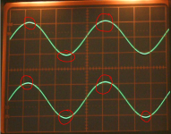
Our hearing is incredibly sensitive to this type of distortion. Take a look at the image here (which I grabbed from one of my threads). This is 1kHz from a function generator and the top and bottom of the sine have a small glitch... bit hard to see in the picture... but this is immediately obvious when listened to as a harsh edge to the sine. Switch to a wien bridge osc (or CD test disc) and the sound is pure.
Thanks for the kind words re the O2. I can't quite remember how I got roped into that thread 😉
Attachments
Hi Kindhornman
I am not trying to disagree with you. I just saw a lot of the designs here including Apex that are 100W to 150W and still use two pairs of transistors. You look at Krell and Threshold, easily 8 to 10 pairs. I don't think it's just for more power. Power also limited by the rail voltage, unless you use like 100V rail, you are not going to get mega watts of power. Most of those amps are like 200W or so. My Acurus is 200W/ch uses 4 pairs and use 80V rail.
I am shooting very high, not just a good amp. I have a good amp already. I already invested way over $1000 just for the parts for this amp, I am shooting for better than Krell and Threshold. This is my hobby, I even consider buying a used Threshold for $1600 just to use as comparison test as my Acurus is only middle of the road. I already have a pair of JMLab 900 series that is on the high end side of speaker( not exotic by any stretch). Even for testing in the small room, I use a pair of Kef, and I still have a pair of Monitor Audio as back up. I am not trying to make a Bryston, Aragon etal, definitely not trying to go with Cambridge Adcom type. If my JMLab proves to be the bottle neck after I have a really good amp, I will upgrade. I might consider the LMLab Utopia or better.
I am not trying to talk big or anything, but this is where I come from. I might not get there in this first amp as I am a newbie, but I will get there. I am not interested in starting small with a single stage blameless. After I design a good SS, I am going to go back to the tubes and build a good tube amp also. I am not going to say money is not an issue, but I am more than prepare to spend some serious money on this hobby. Hope I clarify where I come from.
One mistake I made that is costly. I bought my chassis without knowing the power limit. It is already one of the top on ebay, much beefier than my 200W Acurus. I thought it's good enough. Thinking back, I should have spent more on the chassis as I am limited to about 70W idle dissipation per side with this one and is too much money to just dump it.
Last edited:
Well, I won't call it cool running low bias design, but I am going in direction of more pairs with lower bias each pair. It is proven that more pairs lower the crossover distortion with the same total bias. So if you use more pairs, you can afford to stay reasonable bias and achieve lower distortion.
I am on with a switchable low bias design, currently in the circa 0.009% thd region at <5ma per output device (8 double die lateral FET's per channel, bridge confiuration) and circa 0.0004% at 100ma. Work in progress.
There must be a very good reason why the true high end amps like Krell, Threshold etc. use so many pairs of output transistors.
I think probably because it fits with their design philosophy and their targeted audience.
Putting more pairs on won't make your heatsink any coole overall though, if that's a concern. The thermal resistance from sink to air determines how much it will rise above ambient, even if the devices' junctions on the heatsink end up about at heatsink temp. Device reliability will be a lot better though.
No. More pairs (or equal sources of heat) will lower all junction temperatures. When the number of devices is very large, for the same dissipated power, the junction temperatures are approaching the heat sink temperature.
It is very easy to see why this is happening, the junction temperature is
Tj = To + P*(Rthr-a + (Rthj-c + Rthc-r)/N)
Take a look at the image here (which I grabbed from one of my threads). This is 1kHz from a function generator and the top and bottom of the sine have a small glitch... bit hard to see in the picture... but this is immediately obvious when listened to as a harsh edge to the sine.
Brings memories of my first function gen. Typically for a square wave gen that is turned into a triangle wave through a current source charging/discharging a cap, than a weighted diode network for sine shaping.
ICL8038 or XR2206 I would guess? 😎
Jan
- Home
- Amplifiers
- Solid State
- Bob Cordell's Power amplifier book