...I remember the first time I tried 'pure Cherry' for real in an amp. The residual THD20k showed MUCH clearer xover which disappeared into the noise as you turned Iq up above 20mA...
Yes, of course. If you just move the capacitor connection then the OPS is now inside the loop with the VAS, so more return ratio = lower distortion.
But the OPS pole is now in that loop too, so stability will practically certainly be worse.
If that lower level of stability is acceptable then we can do better if we wrap it around the entire amp.
Yes, these were the ones I meant, you know there is a follow up for the first paper with a non trivial correction?The 2 Cherry papers that discuss this are
4) in Section 3 of 1. says "The only method for significantly reducing S[gm3] is to increase the closed-loop cutoff frequency GTiB/C .. "
Here's where I don't quite understand yet.
Basic result in feedback theory is that the distortion reduction (aka sensitivity in Bode) is the same as the return ratio, multiplied by a factor that depends on the direct transmission.
So if the direct transmission is small then return ratio is all you need to know.
So how come the odd results?
But Iq is FAR LESS CRITICAL in a 'pure Cherry' design and this has implications for stuff with VFETs & also how accurately you need to control Iq too.
This will be true for any scheme with increased return ratio around the OPS, of course.
I need to re-read Cherry now I have revised sensitivity.
Bode's sensitivity definition in equation 4.7 is opaque but Waly's link to the Texas Instrument paper was quite useful.
A pity that he doesn't respond once the questions are difficult, the reference was a lucky bonus from a different subject, worth a look if you missed it.
Best wishes
David
The 2 Cherry papers that discuss this are
- Feedback, Sensitivity and Stability of Audio Power Amplifiers
- Nested Differentiating Feedback Loops in Simple Audio Amplifiers
4) in Section 3 of 1. says "The only method for significantly reducing S[gm3] is to increase the closed-loop cutoff frequency GTiB/C .. "
There's no discrepancy here. Cherry is discussing plain Miller comp. where the Return Ratio is determined 'mainly' by GTIB/C except for 'low' frequencies ... excuse my simplifying this for the unwashed masses, Guru Zan 🙂Here's where I don't quite understand yet.
Basic result in feedback theory is that the distortion reduction (aka sensitivity in Bode) is the same as the return ratio, multiplied by a factor that depends on the direct transmission.
So if the direct transmission is small then return ratio is all you need to know.
So how come the odd results?
diyAudio
I have spent a LO...OONG time trying to find something similar without success 😡 so I'm REALLY interested.
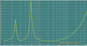
Yes please. An impedance curve would be nice ... preferable to 40kHz cos I think your waveform is pretty HF.
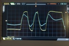
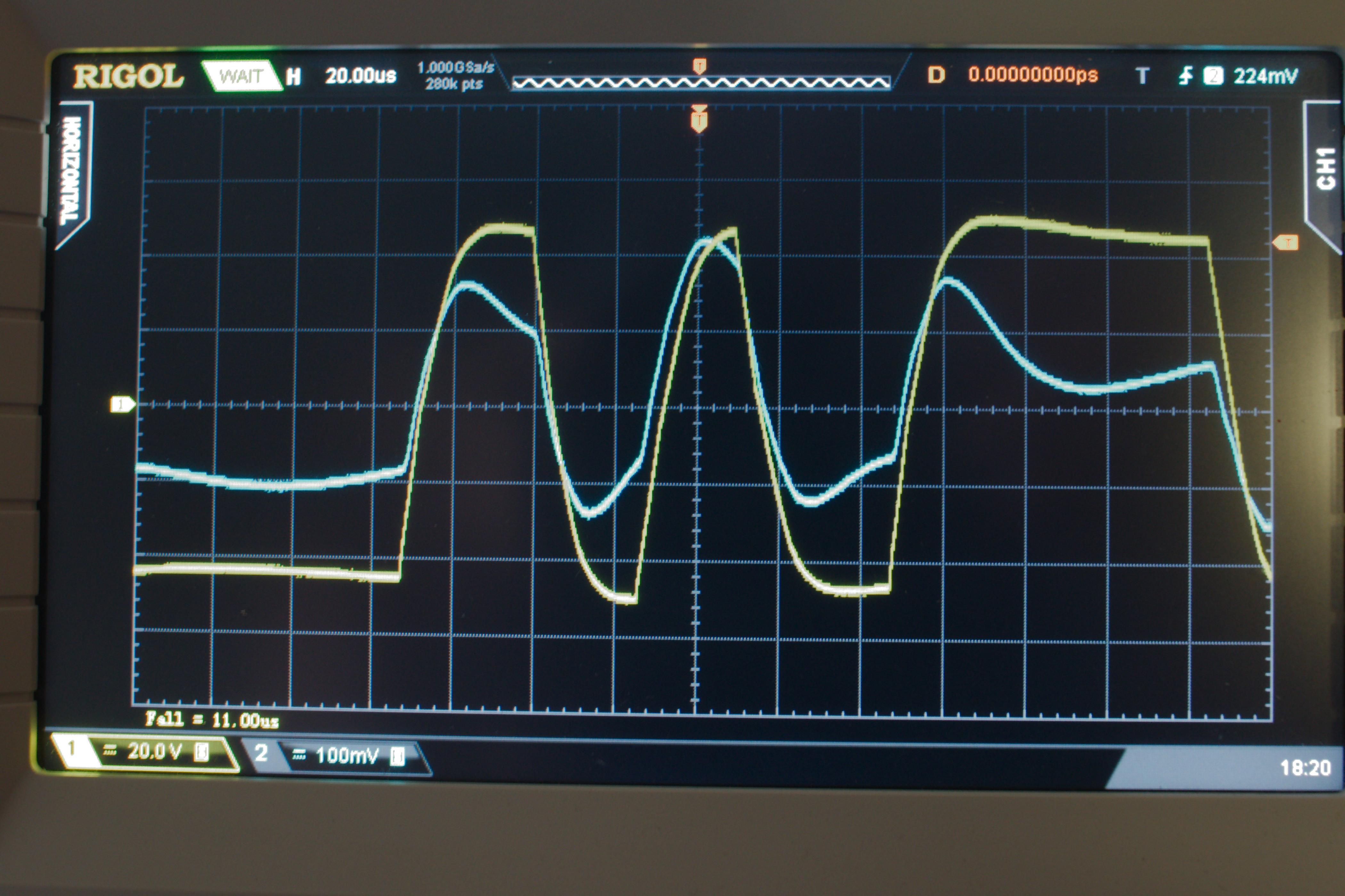
Also is the yellow trace the input signal?
Your blue current waveform doesn't actually show the huge increase in current that Otala (copied by Self & Cordell IIRC) shows with his carefully selected loads & waveforms. 😱
Can you post which CD you found this signal?There it is 🙂 A picture telling more than a 1000 words. The 'load' can also be seen 🙂
I have spent a LO...OONG time trying to find something similar without success 😡 so I'm REALLY interested.
Yes please. An impedance curve would be nice ... preferable to 40kHz cos I think your waveform is pretty HF.
Also is the yellow trace the input signal?
Your blue current waveform doesn't actually show the huge increase in current that Otala (copied by Self & Cordell IIRC) shows with his carefully selected loads & waveforms. 😱
Last edited:
There's no discrepancy here...the Return Ratio is determined 'mainly' by GTIB/C...
No discrepancy on that sensitivity, it's the other ones I don't understand.
It's like when you are a novice, only used to frequency response plots and suddenly the teacher introduces the S-plane and poles and zeros.
At first you don't have a feel for how the different viewpoints are related.
I don't have that feel for Cherry's maths yet but "ma meuf" is overseas so I have some time to occupy.
Best wishes
David
Many years ago, when it starts to be popular,I was playing with LM3875, and I've built a few gain clones non inverting and inverting. I was very satisfied with the sound, but did not pay attention about compensation used.
Attached LM3875 simplified schematic, that could be found in TI datasheets, and it uses "pure Cherry", I am not sure if some other not showed compensation is there?😀
Attached LM3875 simplified schematic, that could be found in TI datasheets, and it uses "pure Cherry", I am not sure if some other not showed compensation is there?😀
Attachments
Many years ago, when it starts to be popular,I was playing with LM3875, and I've built a few gain clones non inverting and inverting. I was very satisfied with the sound, but did not pay attention about compensation used.
Attached LM3875 simplified schematic, that could be found in TI datasheets, and it uses "pure Cherry", I am not sure if some other not showed compensation is there?😀
Very interesting observation. I'm guessing the key word is "simplified".
Notice also they use the "helpered" current mirror to approximately equalize the current mirror collector-base voltages each to 1 Vbe when the 2EF VAS is used (in addition to buffering away the error due to base currents flowing into each of the current mirror transistors).
Cheers,
Bob
LM3875
It's also a Quasi Sym output stage, if that makes any difference ? Note the .45 Ohm Re's too
It's also a Quasi Sym output stage, if that makes any difference ? Note the .45 Ohm Re's too
Looking for low Vbe transistors.
Hi Mr. Cordell
I need your help with your knowledge of semi conductor physics. I am looking for PNP in TO-92 package that has low Vbe on voltage in linear mode( forward reverse bias). datasheet usually does not give this parameter. My experience is looking for high Ic does not necessary imply low Vbe. What parameters should I look for? How is Vce saturation voltage relate to Vbe on in linear mode? How does Vce max affect the Vbe? How is hfe affect the Vbe?
I am running into a lot of problems with my 3EF Diamond OPS. The first one is the low spreader voltage requirement. With the MJW1302/3281, I only need 1.1V for the spreader. This make it very hard to keep the spreader at this low voltage and still get -4mV/deg C as the multiplier ratio is only 1.1/0.65=1.7. That will only give -3.4mV/deg C. I ran into Iq increase as temperature goes up. I need to use CFP and adjust the collector resistor of the NPN spreader to massage to get the right tempco. Both transistors need to have low Vbe to prevent the NPN from saturating.
What made it worst is when I test the OPS for frequency, the pre-driver stage ran out of current when frequency goes above 700KHz because the current source is finite, not like the regular 3EF that the pre driver can drive hard. I need to increase the current, but that increase the Vbe of the pre driver, which eat into the spreader voltage. After I increase the current, the spreader need to be lowered to 0.9V!!!! I can't get the NPN out of saturation!!!.
Is that the reason people don't use 3EF diamond? I have not seen a circuit here using that. People rather deal with 6Vbe spreader and deal with all the thermal issue than to use 3EF diamond.
Thanks
diyAudioCan you post which CD you found this signal?
I have spent a LO...OONG time trying to find something similar without success 😡 so I'm REALLY interested.
Yes please. An impedance curve would be nice ... preferable to 40kHz cos I think your waveform is pretty HF.
Also is the yellow trace the input signal?
Your blue current waveform doesn't actually show the huge increase in current that Otala (copied by Self & Cordell IIRC) shows with his carefully selected loads & waveforms. 😱
It was a test-track of one of the 'Stereo Play' (German magazine) CD's that I have here, the test-track contained a recording of an motorized ground-stamping-machine (I have no idea how to call these) (you know the thing they use to firm up the ground when laying brick work).
Both waves are output signal, the yellow trace is output voltage at 20V/div and the blue trace is current at 10A/div.
Attachments
The Roender output stage needs 4 Vbe compensation.
It runs a pre-driver/driver stage as a CFP and then adds on the EF as the output stage.
The CFP only requires (significant) tempco of the pre-driver.
Roender use 5 off TT diodes run at lowish current to compensate the CFP+EF stage.
It runs a pre-driver/driver stage as a CFP and then adds on the EF as the output stage.
The CFP only requires (significant) tempco of the pre-driver.
Roender use 5 off TT diodes run at lowish current to compensate the CFP+EF stage.
watching that type of machine in action is impressive.It was a test-track of one of the 'Stereo Play' (German magazine) CD's that I have here, the test-track contained a recording of an motorized ground-stamping-machine (I have no idea how to call these) (you know the thing they use to firm up the ground when laying brick work).
Both waves are output signal, the yellow trace is output voltage at 20V/div and the blue trace is current at 10A/div.
I had seen a video of a 5tonne stomper dropping 10m, but some years later I saw the real thing !!!!
The height of "drop" is a rough indication of the depth effect for the compacting of the looser soil material.
Much cheaper than piling, if one does not need the potentially high load capacity of the pile method.
FET equivalent of Ft
Hi Bob
A quick question on a calculation in the book, perhaps just due to my inexperience with FETs.
On p. 222 you calculate the equivalent Ft from the time constant of the FET input capacitance and the transconductance.
Then you mention the gate resistance, almost as an additional adjustment.
Since the gate resistance is typically 10 or more times the inverse transconductance, why does it not dominate?
Why is the equivalent of Ft not set by the time constant of the input capacitance and the base resistance?
Your table 11.3 show the transconductance Ft of a lateral FET as 250 MHz but the text in the previous section above it says "a typical lateral power MOSFET is down 3 dB at 2.5 Mhz"
Seems inconsistent, have I missed some point?
Best wishes
David
Last edited:
could the 2.5MHz be a misprint...
I don't think so, in the context of the lower frequency response to be expected from the increased base resistance of lateral FETs.
But the number is a mystery.
If a transconductance of 1 S leads to an Ft of 250 MHz then the 40 ohm base resistance quoted should lead to closer to 6 MHz.
Best wishes
David
Hi Bob
A quick question on a calculation in the book, perhaps just due to my inexperience with FETs.
On p. 222 you calculate the equivalent Ft from the time constant of the FET input capacitance and the transconductance.
Then you mention the gate resistance, almost as an additional adjustment.
Since the gate resistance is typically 10 or more times the inverse transconductance, why does it not dominate?
Why is the equivalent of Ft not set by the time constant of the input capacitance and the base resistance?
Your table 11.3 show the transconductance Ft of a lateral FET as 250 MHz but the text in the previous section above it says "a typical lateral power MOSFET is down 3 dB at 2.5 Mhz"
Seems inconsistent, have I missed some point?
Best wishes
David
Hi Dave,
This is a good question, and I will look back at what I have written to make sure it all makes sense and to also add clarification needed to answer a question like this.
One key thing is that I use the term "equivalent ft" because I am defining it in the same way as for a BJT in its hybrid pi model, where ft (radian measure) is the ratio of transconductance to Cbe. Traditionally, in talking about ft for BJTs we think of it as the frequency where the current gain goes down to unity. Thus the concept of ft has to do with current gain, not voltage gain.
If we "measure" the ft of a MOSFET, we feed the gate through a current source so as to measure its "current gain". In such a situation, to first order, the gate resistance does not matter, since a current is being passed through it to make the measurement if we are measuring current gain. Of course, we don't think much in reality of current gain of a MOSFET, so the concept of ft is not a perfect fit. Nevertheless, it is a useful indication of potential speed.
Now let's think in terms of a MOSFET driven from a voltage source. We are no longer talking about current gain and RG DOES matter. We are now talking about the frequency response of the transconductance. RG affects the frequency response of transconductance and in turn affects the useable speed of the MOSFET. Here thinking of the MOSFET in a commons source arrangement may be best. However, even in common drain, the Cgs is just bootstrapped to a smaller effective value by the closeness of the stage gain to unity.
ft and transconductane frequency response are two different things, but they both contribute to the bottom line of useable speed.
Bear further in mind that the use of gate stopper resistors is not unlike having an even larger total gate resistance, once again reducing transconductance frequency response as seen at the input side of the gate stopper resistor.
Finally, and especially with lateral MOSFETs, RG in the device is distributed, almost somewhat like a distributed R-C transmission line. This can create a rather "blurred" phase delay, with different portions of the transconductance-creating areas of the device receiving "inputs" with different amounts of phase lag. Of course, the distributed R-C delay line creates numerous poles which, together, look like different amounts of pure delay.
To the extent that the distributed RC nature of the gate in a lateral MOSFET is a big player in the speed of the device, this suggests that the SPICE model for the lateral MOSFET may fall somewhat short.
Cheers,
Bob
If we "measure" the ft of a MOSFET, we feed the gate through a current source so as to measure its "current gain". In such a situation, to first order, the gate resistance does not matter, since a current is being passed through it to make the measurement if we are measuring current gain. Of course, we don't think much in reality of current gain of a MOSFET, so the concept of ft is not a perfect fit. Nevertheless, it is a useful indication of potential speed.
I can't even imagine injecting a current in the mosfet gate, what's the point of this thought experiment?
Defining Ft for bipolars as the ratio of transconductance to Cbe makes sense because it's more or less bias independent*), since both the transconductance and Cbe depend on Ic (both increasing with increasing Ic). For mosfets, this falls flat. Your "ft" for mosfets will strongly depend (always increasing) on Id which makes this "definition" inept.
There is a fundamental reason why mosfets are intrinsically much faster that bipolars: they are majority carriers devices, and do not suffer from any excess charge and recombination effects. But that's not something that your book target audience, the DIY community, will easily digest, so instead of inventing false analogies, you'd be better leaving it at a simple statement level: mosfets can be much faster than bipolars. I don't think anybody in your target audience will question this.
*) At least for a range of collector currents in the common operating range, for a particular device.
Last edited:
I can't even imagine injecting a current in the mosfet gate, what's the point of this thought experiment?
Defining Ft for bipolars as the ratio of transconductance to Cbe makes sense because it's more or less bias independent*), since both the transconductance and Cbe depend on Ic (both increasing with increasing Ic). For mosfets, this falls flat. Your "ft" for mosfets will strongly depend (always increasing) on Id which makes this "definition" inept.
There is a fundamental reason why mosfets are intrinsically much faster that bipolars: they are majority carriers devices, and do not suffer from any excess charge and recombination effects. But that's not something that your book target audience, the DIY community, will easily digest, so instead of inventing false analogies, you'd be better leaving it at a simple statement level: mosfets can be much faster than bipolars. I don't think anybody in your target audience will question this.
*) At least for a range of collector currents in the common operating range, for a particular device.
You are correct - the equivalent ft for a MOSFET increases with current, and I will make that more clear in the second edition.
The use of equivalent ft is not inept - it is useful as a figure of merit, and since it is for MOSFETs, I use the term "equivalent". You should also be aware that the equivalent ft is also applicable for JFETs, and there has been that term used for JFETs as well, not just by me.
Yes, majority carrier devices have higher potential speed than minority carrier devices, and I will try to make that more clear in my second edition as well. The DIY and pro audio community to whom this book is aimed is fully capable of understanding those concepts, including carrier mobility, if it is explained in a helpful way.
Cheers,
Bob
The DIY and pro audio community to whom this book is aimed is fully capable of understanding those concepts, including carrier mobility, if it is explained in a helpful way.
Perhaps many would understand, but certainly very few would care about such an explanation. Wouldn't it be so much better to quote a reference and leave it there...
Perhaps many would understand, but certainly very few would care about such an explanation. Wouldn't it be so much better to quote a reference and leave it there...
No, Waly. As far as speed goes for a MOSFET, the ratio of transconductance to gate capacitance is a very useful indication of speed. That is equivalent ft and is useful when characterizing the speed of MOSFETs to BJTs. It is valid for a given operating point (of course, BJT is also somewhat a function of operating point, but not quite in the same way).
Where you always fall short is that you criticize something but do not present an alternative that is better.
Waiving your hands about majority carriers et al is entirely useful, but completely non-numerical unless you want to get into a level of physics that is not useful for the purpose in a forum or audience like this.
How's your book coming?
Cheers,
Bob
- Home
- Amplifiers
- Solid State
- Bob Cordell's Power amplifier book