Alan,
I wouldn't tell you to dump your chassis, but perhaps you can just change the heatsink to one with better dissipation properties. More mass and more surface area can make a big difference and as long as you can fit it to your chassis that is much cheaper than an entirely new chassis. Perhaps you can list the size of your chassis so you can get some recommendations for a heatsink upgrade. The Chinese heatsinks are many times less effective than a domestically made extrusion even of the same size.
I wouldn't tell you to dump your chassis, but perhaps you can just change the heatsink to one with better dissipation properties. More mass and more surface area can make a big difference and as long as you can fit it to your chassis that is much cheaper than an entirely new chassis. Perhaps you can list the size of your chassis so you can get some recommendations for a heatsink upgrade. The Chinese heatsinks are many times less effective than a domestically made extrusion even of the same size.
Alan,
I wouldn't tell you to dump your chassis, but perhaps you can just change the heatsink to one with better dissipation properties. More mass and more surface area can make a big difference and as long as you can fit it to your chassis that is much cheaper than an entirely new chassis. Perhaps you can list the size of your chassis so you can get some recommendations for a heatsink upgrade. The Chinese heatsinks are many times less effective than a domestically made extrusion even of the same size.
This is the one I have. This ask for less, but $100 shipping to prevent you from returning it!!!🙄 I don't know why they called this small chassis!!! It's nothing small about it.
4015 A New Small Aluminum Chassis Class A Amplifier Chassis Amplifier Case Ext | eBay
The heat sink is part of the chassis, I am not sure you can find one to fit perfectly. It's heavy, the bottom plate is very thick also.
Now, this is a chassis!!!:http://www.ebay.com/itm/Large-alumi...al&tfrom=281368571725&ttype=price&tpos=unknow
Last edited:
But there are LOADSA low bias designs that are indistinguishable sonically from higher bias designs ... in DBLTs. 😱I'm surprised that no one is working toward a cool running low bias design that actually is indistinguishable sonically from the higher bias designs.
For similar performance in sighted tests, the important ingredient for these low bias designs is the Hand carved from liquid Unobtainium by Virgins label. 🙂
Xover might have been the ...
in the 60's ... when DBLTs were used to check this, but it isn't now unless the design is really incompetent.dominant problem of the power amplifiers
Alan, for how to do amps with little or no xover without using zillion output pairs & zillion Amp Iq, have a look at [url]http://www.diyaudio.com/forums/solid-state/235188-tpc-vs-tmc-vs-pure-cherry.html[/URL]
If you are really interested in audible problems in Power Amps, you might want to look at the DBLTs that HAVE been conducted on them.
But if High End rather than Good Sound is your aim, I think you are right on target. 😉
_______________________
BTW, Self DOES have loadsa good stuff about Thermal Gain though not quite as comprehensive as Bob Cordell .. and I don't think either take full advantage of their supa tools (eg Doug's LTspice thermal circuit equivalent)
Bob, this might be worth a page or two in your next edition. Perhaps a detailed thermal analysis of a simple one BJT pair 50W amp with single spreader ... and a less sensible one with zillion output pairs .. with suitable acknowledgement of Alan who did the practical tests for the later 😀
While I hesitate to suggest an EE of 33 yrs standing, (who dreams up a less than 50W output stage with Thermal Runaway in the 21st century) is representative of the unwashed masses, this might help those of us who kunt reed en rite place your pontificating on Thermal Gain into context. 🙂
This is the one I have. This ask for less, but $100 shipping to prevent you from returning it!!!🙄 I don't know why they called this small chassis!!! It's nothing small about it.
4015 A New Small Aluminum Chassis Class A Amplifier Chassis Amplifier Case Ext | eBay
The heat sink is part of the chassis, I am not sure you can find one to fit perfectly. It's heavy, the bottom plate is very thick also.
Now, this is a chassis!!!:Large Aluminum Amplifier Case Chassis Enclosure Ref Krell KSA 250 480 215 520mm | eBay
There is, but not used method of shipping chassis. BY SHIP. Why I would like to know do the Chinese insist upon shipping heavy items like chassis by AIR. I would be willing to wait a MONTH for a decent shipping price/cost. But they insist on AIR. Does anyone know WHY? There are thousands of containers coming into many USA ports daily...😀
help those of us who kunt
(I bet that's a cheeky one to oogle image, but thank goodness it's a dutch word)
I bought the entire NOS R-core transformer stock of THL audio in Taiwan. Had they not been willing to ship them out by cargo vessel, it would have been a way less pleasant buy, despite the 3 month wait.
Last edited:
While I hesitate to suggest an EE of 33 yrs standing, (who dreams up a less than 50W output stage with Thermal Runaway in the 21st century) is representative of the unwashed masses, this might help those of us who kunt reed en rite place your pontificating on Thermal Gain into context. 🙂
First it's not a 50W amp, it's higher. As standing, it's going to be over 150W at 40V rail. Second, it took me less than a day to fix that and fixed it good without any help of this. I went back and read both books, I don't see any warning about matching Vbe between spreader transistor and power transistor. I did discovered and fix it in less than a day. I think both books need to add this problem and how to fix it. I did not see any temperature compensation for 3EF Diamond that I use. None of the stuff in Cpt 14 of Mr. Cordell's book help me.
I can't hear all the other amps, only the real high end amps. On top, you need to have super good speaker too.
Last edited:
How do you manage to get 150W from 40V rails..?? According to my calc you can get app 100W where my 56V will get you to 200W
How do you manage to get 150W from 40V rails..?? According to my calc you can get app 100W where my 56V will get you to 200W
4ohm speaker that I have.
I am not convinced at all I need high power. All the high end tube amps I heard were below 50W. The most impressive one was Cary single end that was less than 10W. People can say what ever, I did listened in the show room with my own CD on a pair of Sonus Fabers and it was impressive. It was quite loud also.
I use diodes in VAS to prevent clipping exactly the same as Bonsai to prevent sticking, we'll see how that works.
The YBA amp that got me into all these was only 70W. The sound was jaw dropping. I had my Acurus side by side with that on my speakers, I immediately kicked myself buying the Acurus. It was too late as I bought it months before.
Last edited:
There is, but not used method of shipping chassis. BY SHIP. Why I would like to know do the Chinese insist upon shipping heavy items like chassis by AIR. I would be willing to wait a MONTH for a decent shipping price/cost. But they insist on AIR. Does anyone know WHY? There are thousands of containers coming into many USA ports daily...😀
I don't know whether they shipped air to me, it did take a long time ( over a month) to arrive. The price of this chassis is always between $250 to $280 total, some have higher price and low shipping, the one I got I managed to talk it down to $125 but still $140 shipping. I think they ship by liners, just jack up the shipping to prevent you from returning it. If I return it, they still earn a lot of money. The one I have has all the holes for the input jack and output jacks drilled, not like these new batch that only have the power inlet. It is of very high quality for sure, better than all the middle of the road amps I've seen in the store.
Last edited:
... and into a highly reactive load - often the largest multi-way expensive speakers have a large reactive component.
True, but we're DIYers here! It would likely be a lot easier to flatten the impedance of a loudspeaker to a better range than to mount and wire big numbers of devices onto a heatsink. Measuring a loudspeaker's impedance is trivial anymore with things like WooferTester or DATS, and with such a curve it is pretty easy to find a good shunt network to put across the impedance with <ahem> my XSim designer/simulator.
Edit: This won't work, of course, on speakers with crazy impedances that dip way low or act like a big capacitor at HF. A network across the terminals is only going to lower the impedances of the high points to the middle or average, won't bring up the dips put in by designers who should know better...
Last edited:
True, but we're DIYers here! It would likely be a lot easier to flatten the impedance of a loudspeaker to a better range than to mount and wire big numbers of devices onto a heatsink. Measuring a loudspeaker's impedance is trivial anymore with things like WooferTester or DATS, and with such a curve it is pretty easy to find a good shunt network to put across the impedance with <ahem> my XSim designer/simulator.
But speaker is even more important than the amp in the system, how can you change the impedance of the speaker load without messing up the sound? Pretty much you get the speaker, then match the amp. That's what I am doing right now. I design the amp for the speaker. Speaker is where you put the big money.
I happened to have a chance of side by side comparison of my Acurus with the YBA when I was buying my pair of speakers, that's the reason I know how big a difference it make if I get a better amp.
Ha ha, I don't need blind test, that YBA looked so small and cheap, I never even took a second look until the salesman switch to my Acurus to final tested the speakers. It was jaw dropping difference.
Last edited:
You can put a network across the speaker terminals to lower impedance peaks (which look for all the world like resonances). The speaker still directly sees the amp's output, the amp sees the speaker and the network. Best for use with amps that have low damping factor, but other amps may work better if the load looks more like a resistor than a pile of reactances.
Were the levels (amp gains) matched when you compared? People will generally find the setup played at more than a few tenths of a dB higher to sound better. Not that it's impossible to go the other way, but if there's no difference than level, then usually an impressive improvement is heard.
Were the levels (amp gains) matched when you compared? People will generally find the setup played at more than a few tenths of a dB higher to sound better. Not that it's impossible to go the other way, but if there's no difference than level, then usually an impressive improvement is heard.
Last edited:
You can put a network across the speaker terminals to lower impedance peaks (which look for all the world like resonances). The speaker still directly sees the amp's output, the amp sees the speaker and the network. Best for use with amps that have low damping factor, but other amps may work better if the load looks more like a resistor than a pile of reactances.
Were the levels (amp gains) matched when you compared? People will generally find the setup played at more than a few tenths of a dB higher to sound better. Not that it's impossible to go the other way, but if there's no difference than level, then usually an impressive improvement is heard.
Did you try the shunt network and see whether it affect the sound.
I did not pay attention of the exact level, it was comparable in loudness. It was in 1998 or 1999. at the time, I was not into power amp at all. I thought the speakers were the only thing that was important, the amp meant nothing. I got the Acurus for the pair of floor standing Kef when my old SAE kind of dying. I bought the Acurus to replace that. It did improved the sound but nothing worth writing home( it turned out the speaker cable was the problem, I did not have 12 gauge cable at the time).
Then I decided to go for the JMLab 900 to replace the Kef. I never even thought about the amp until I was closing the deal on the speaker and I want to bring my Acurus over to test to make sure everything worked. That's the time when they replace my Acurus in and heard the stunning difference. I switched back to the YBA and proved it's the amp. That's was the first time I realize the amp is just as important.
I want to mention one more thing. when they delivered the JMLab, I hooked it up, it was no better than my Kef!!! I was distressed!!! All that money and no improvement!! Then I started to experiment with the speaker cable. I changed to the first pair of 12 gauge, the sound opened up a lot. I kept adding more pairs, it still improved. It stop improving after the 4th pair of 12 gauge cable!!! This is not psychosomatic, my wife who didn't know anything ( still does know) about hifi could tell too.
It is my believe the system is only as good as the weakest link. If your speaker is not good enough, you won't hear the difference, you can get away with lesser amp and lesser cables. When you have better amps, cable might be even more important. When I hooked back the Kef with the new cables and amp, it really did not open up. Then it became day and night difference between the JML and the Kef.
In fact, I went into the Kef and double up all the wires inside, I use wires to beef up the traces of the crossover pcb. I did it on one speaker and I compared with the un-modified one side by side. It did seem to open up a little after going back and fore many times. I then modified the other one, then they sounded the same. that's the reason I always overkill the wires and pcb traces on the high current signals.
Last edited:
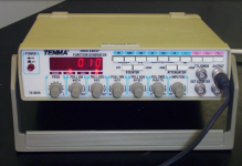
Brings memories of my first function gen. Typically for a square wave gen that is turned into a triangle wave through a current source charging/discharging a cap, than a weighted diode network for sine shaping.
ICL8038 or XR2206 I would guess? 😎
Jan
Yep, plenty of diodes but the generator is a Tenma 72-5015, mainly discrete (quite a few transistor arrays- CA4046/56 from memory) and quite complex actually, but it does have the diode strings easily visible on the pcb.
Attachments
Originally Posted by AndrewT View Post
I have suggested a 10pr MJE15034/5 output stage a few times on this Forum.
That gives a 1kW stage, which results in a 200W ClassAB amplifier.
the mje15034/5 are 50W BJTs.By 1KW, do you calculate from 10pr of 100W transistors?
...................
10pr equal 20 devices and that amounts to 1kW of devices.
Using my standard guide developed from Bensen's spreadsheet, I divide that by a factor varying from 4 to 6, to find the maximum reliable power output.
For a good soa BJT I use the factor 5, for poor (1943/5200), or very hot BJT, I use a factor of 6 and for mosFETs I use a factor of 4.
This gives a very similar result to R.Cordell's divide by 75 method shown in the interview Thread.
1pr of 250W (MJ15004) BJT are good for a 100W amplifier.I just saw a lot of the designs here including Apex that are 100W to 150W and still use two pairs of transistors.
2pr of 180W devices are good for a 144W amplifier
2pr of 150W 1943/5200 are good for a 120W into 4ohms but decreases to 100W into 8ohms due to the higher stress of the higher supply rails.
Last edited:
You tested via a real speaker.
Pass the instantaneous peak current info on to the Cordell book Thread.
Some in there will not believe that peak current can ever exceed Vpk / (lowest real resistance of the speaker)
i.e. they insist that if a real 8ohms speaker has a resistance of 6r, then the peak current can never be more than Vpk/6
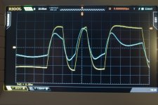
This is a 100W (+-50Vcd PSU) amplifier in normal operation. The blue trace is from the current probe and measures 10A/div (the maximum current shown is about 22A). Braking even normal operation, with an relay, is difficult under stress it will be even more difficult.
What is the load during this measurement?
100W into 8r0, or 8ohms(with some L&C), or 4r0, or 4ohms(with some L&C)?
The load is a 8-ohm (nominal) loudspeaker system. Carver Amazing Platinum Edition. This is an magneto stat (2 pcs 70cm(28") line sources) with 4 cone (25cm(10") diameter) woofers in a panel.
There it is 🙂 A picture telling more than a 1000 words. The 'load' can also be seen 🙂
Attachments

re post 6616
The 22Apk from a 100W amplifier into 8ohms speaker indicates an effective impedance of 1.82ohms., (40Vpk/22Apk = 1.82ohms)
If I change the driving voltage to 47Vpk, then the effective impedance becomes 2.14ohms.
The 22Apk from a 100W amplifier into 8ohms speaker indicates an effective impedance of 1.82ohms., (40Vpk/22Apk = 1.82ohms)
If I change the driving voltage to 47Vpk, then the effective impedance becomes 2.14ohms.
re post 6616
The 22Apk from a 100W amplifier into 8ohms speaker indicates an effective impedance of 1.82ohms., (40Vpk/22Apk = 1.82ohms)
If I change the driving voltage to 47Vpk, then the effective impedance becomes 2.14ohms.
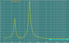
I'm sure it is back-emf that creates the behavior. I did try to find the measured impedance graph of the loudspeaker but could not find it, the impedance meter is at the moment not here. So one has to give this a bit of time.
If I understood the non believers correctly, then you don't need an impedance value. They claim that the DC resistance defines the worst case peak current demand.
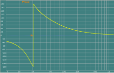
But if they meant the minimum impedance just above the resonant impedance peak where reactance is now zero (phase has returned to zero degrees), then impedance at this frequency will need to be measured.
By the way it's a fairly easy value to find and measure. Just look for and measure the lowest voltage across the speaker after feeding the test signal in via a 1k0 resistor.
Because phase has returned to zero the reactance is also zero and thus the value measured is the non reactive impedance.
The low point is likely to occur in the frequency range from 100Hz to 300Hz. And it will be quite a broad minimum so even a small frequency error still allows one to get a reasonably close estimate of this impedance low.
Last edited:
- Home
- Amplifiers
- Solid State
- Bob Cordell's Power amplifier book