I just redid a bunch of calculations and contemplating of where to set margins.
The problem with 0.1R degeneration resistors is that at 60V rails they are only really thermally stable at idle bias. If the bias goes up, it is almost impossible to make them stable.
The problem with this is that, for a worst case Tj of 150C, the bias will jump 330mV for several seconds before the thermal compensation can kick in. Since current hogging occurs at the junction, it can be over in 100mS. So you have a period of several seconds before the Vbe multiplier kicks in where current hogging is likely to occur.
So really, we should be calculating thermal stability at 150C before the Vbe multiplier kicks in. When you do this you discover that there are benefits to going larger than even 0.22R. Matched 250W BJTs at 60V mounted directly to a heat spreader can just barely handle 150C without current hogging, based on my estimations.
Does any analysis tools exist that are capable of analyzing a smallish 20Khz tone riding on top of a higher amplitude lower frequency carrier... Like 100-200 Hz 80V-pp. I believe that if you do that you'll find a big difference between VFA and CFA.
I can do this in the simulator. Sometimes I simulate a 1KHz sine wave with a 25mV 100KHz triangle wave added to it to imitate SMPS ground noise. Sometimes this will increase distortion dramatically.
When you do this you discover that there are benefits to going larger than even 0.22R.
(higher Re values for output stages outside the global feedback loop in fancy Japanese selected parts designs, would suggest they view low emitter resistance of inferior significance)
When you look at the amplitude/frequency of a music signal, the you'll see a 1.order decrease in amplitude starting at app. 1Khz. So it will make sense to analyse multi-tone signals. I would really like to see how a high frequency signal behaves when its riding on top of a large lower frequency signal. But I don't know how to get any good results from that.
MIIB,
Twin tone harmonic testing is usually done with closely spaced tones, let's say 19khz and 20khz to see any IMD type of distortion so I don't see why what you are trying to do is really different besides the spacing of the frequencies?
I would think there is already some open source software that can do what you are looking to do with sine waves.
Indeed. I'm surprised it's taken this long for someone to point that out.
Alan needs to read chapter 14 of Bob's book more carefully. In particular, section 14.8 talks specifically about manipulating the temperature coefficient of the bias spreader.
Perhaps for his second edition, Bob could consider addressing some of this earlier in the chapter, as the issue of tempco is relevant whether the output stage is using ThermalTrak transistors or not.
Be careful with section 14.8 as there some ThermalTrak spreaders errors. All schematics are correct but the calculation of the temperature coefficient (Sttd) is wrong in figures 14.19a and 14.19c. R1 does not influence Sttd and that one should be used to set the bias.
Damir
You also explained it to me on the DIYAudio What is a CFB amplifier discussion.... which spun off at least two other designer subjects. Your description of getting/trimming the bias for constant idle was quit clear, I thought. But dont remember where in the forum it is. Glad it is also on your own web site.
It is the only such description for proper bias operation ref thermals I ever saw. With credit to you, it ought to be in every book published on audio design.
THx-RNMarsh
Thank you
🙂
how i control biascurrent
I read everything you guys do write and learned a lot..
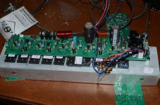
Here is my bias control (fully tested).
The principle is AC canceling!!!!!!!
I use the same type of circuit in my offsetcontrol (servo offsetcontrol) it works way better at low frequencies because of the AC canceling.
see attachment
greet Marius van den Berg.
I read everything you guys do write and learned a lot..
Here is my bias control (fully tested).
The principle is AC canceling!!!!!!!
I use the same type of circuit in my offsetcontrol (servo offsetcontrol) it works way better at low frequencies because of the AC canceling.
see attachment
greet Marius van den Berg.
Attachments
Indeed. Current through bias spreader is equal to current source current minus what goes to the output stage. Check out the device data sheets. Minimum gain for that amplifier's output stage is not that high so bias spreader current variation could be significant.
I did a quick LTspice sim. See attached, comparing R12 present and not present. X-axis is current through bias spreader, y-axis is developed voltage. I used Bob's MJE340 model but the voltage developed looks a bit high to me (this is with PR1 = 0 ohm), however the sim still shows the principle. In simulation land, voltage vs current is flattened with R12 = 150R. Of course for the "flat" case voltage developed is also lower so R12 value and developed voltage have to be iteratively optimised. I'm sure Doug optimised this in "real life" rather than the simulator!
I see now how R12 can indeed be involved in the thermal design. In this case, rather a large R12 value is required to give a "flat" voltage vs current characteristic. Other designs I've evaluated, do not requre R12 to be as large so its effect in that case is much more to flatten the V vs I curve rather than manipulate the thermal response.
Harry, I think the thermal response of a triple + associated heatsink(s) is quite complex and highly dependent on the mechanical design. For example, if the system response is fast (a few seconds), I suspect the 'curve flattening' requirement of R12 to be low. Further, the spreader gain and the standing current in the OPS devices will also play a significant part in the system response. L
The whole subject of thermal comp indeed requires more investigation IMV.
Last edited:
MIIB,
Twin tone harmonic testing is usually done with closely spaced tones, let's say 19khz and 20khz to see any IMD type of distortion so I don't see why what you are trying to do is really different besides the spacing of the frequencies?
There are two “defined” IMD tests - SMPTE standard RP120-1983, and the CCIF/ITU-R IMD test. The latter is the 19 kHz + 20 kHz equal amplitude test, whilst SMPTE is 60 Hz + 7 kHz in a 4:1 amplitude ratio, so very much like what MiiB is suggesting.
For further info see Rane note 145.
Harry, I think the thermal response of a triple + associated heatsink(s) is quite complex and highly dependent on the mechanical design. For example, if the system response is fast (a few seconds), I suspect the 'curve flattening' requirement of R12 to be low. Further, the spreader gain and the standing current in the OPS devices will also play a significant part in the system response. L
Note that the amplifier in question is not a triple, just a darlington.
I would have thought that the bias spreader voltage changing with current could cause additional distortion for high-amplitude signals into low impedance loads.
The whole subject of thermal comp indeed requires more investigation IMV.
Indeed, it’s fascinating. The sheer number of parameters that must be accounted for to me suggests that, for the very highest performance systems, either a sliding bias controller is required (which immediately eradicates any need to track temperatures etc), or the previously discussed uP approach. Both approaches also have the appealing prospect of a system that requires no trimming at time of manufacture.
BTW - thanks for your write up on the issue - excellent as usual!
The 'Bowers Test ' looks for system stability in the face of small signal parametric shifts brought about by changes in the large signal operating point of an amplifier.
Use a low freq sine wave signal swinging to 80% of the supply rails and impose on this a high frequency square wave of 200 to 500 mV pk-pk. Ideally, the square wave HF signal should be reproduces accurately without overshoot, ringing or any other anomalies. You should only do this test after compensating the amplifier conventionally.
Use a low freq sine wave signal swinging to 80% of the supply rails and impose on this a high frequency square wave of 200 to 500 mV pk-pk. Ideally, the square wave HF signal should be reproduces accurately without overshoot, ringing or any other anomalies. You should only do this test after compensating the amplifier conventionally.
Note that the amplifier in question is not a triple, just a darlington.
.
.
.
BTW - thanks for your write up on the issue - excellent as usual!
Thank you. Time permitting, I would like to take the uController concept further.
DBLTs that HAVE been carried out on amps and their implications for design. Jan_Didden has been involved in some this Millenium and they confirm stuff that I was involved with in the previous century. WARNING : results are heretical to both audiophools & objectivists 😱
This is the DBLT stuff which I referred to earlier and there is good 'objective' criteria and backing for having this in your book.
The bandwidth limitation stuff is of course heretical to both objectivists & Golden Pinnae alike but I think you should at least mention it as the properly gathered hard evidence appears to be unanimous. 😱
But I'm not asking for debate .. only that you list whatever tests are in the public domain & their results.
Please could you provide the relevant references? I am very interested but have no idea which tests you are talking about or where to find the published results.
This is important cos the objectivists AND the Golden Pinnae have banded together to stamp out all trace of these results, heretical to both their faiths. 😱
I don’t see how the results of a properly-conducted DBLT could possibly be against the “faith” of objectivists. I hold that:
1. It is plausible that any difference in amplifier behaviour that is measurable could possibly but doesn’t necessarily cause an audible difference.
2. That measurements are the best way to determine an amplifier’s fidelity in the most literal sense.
3. What “sounds good” is not necessarily maximum fidelity.
4. If an amplifier is clipping during music playback, it is no longer high fidelity (output is no longer faithfully following input).
5. An amplifier’s behaviour during/after clipping is important, assuming that it is a design where clipping is a realistic possibility (i.e., most domestic HiFi).
Ideally, the square wave HF signal should be reproduced accurately without overshoot, ringing or any other anomalies
This is debatable. Overshoot and/or (damped) ringing by themselves, are IMHO not a problem. High-order systems can have impulse responses with overshoot/damped ringing even with good phase and gain margins. Very large overshoot or undamped ringing shows instability is occurring.
Overshoot and ringing tend to be avoided in things like power supply design, as the power supplies could be subjected to transient changes in operating conditions such as sudden load or line changes. With an audio amplifier things are a bit more predictable and the input signal can be low-pass filtered such that the demand the amplifier sees is band-limited to the frequency range where the amplifier has a flat response.
Miib, if you have a 100KHz tone and a 1KHz tone, then the 100KHz tone will have sidebands at 101kHz, 99kHz, etc. Look at the magnitude of these, maybe that is what you are after? These frequencies will tell you how much the 100KHz tone is being modulated by the 1KHz tone.
Hi
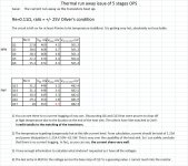
As promised, I redo the testing using Re=0.11ohm. Here is the result.
1) I adjust to Oliver's condition which is about 250mA/stage and total of 1.25A.
2) I run 25V rail, it is getting dangerously hot as it is 62.5W on this small heat sink.
3) I waited for 45mins for the circuit to get hot and stablized before I did the measurement.
4) The circuit is ROCK STABLE from room temp to untouchable hot. The voltage across the Re did not vary more than 2mV from cold to hot. Using the MJW transistor works perfectly.
5) There is absolutely no current hogging, as from yesterday, Q6 and Q17 being at the cooler side, pulling a little less current than the others. The Vbe of the rest of the 4 NPN and 4PNP both have Vbe matched to 2mV.
6) The first column of the table is the voltage across the Re, second column is Vbe of that transistor, third column is the voltage across the base stop resistor.
7) The 4th column is the sum of the first three column. This is what AmdrewT wants to plot the graph.
8) The voltage of base stop for Q17 in RED is my guess, I could not reach it.
My conclusion is you can use 0.1ohm as in my case of 0.11, there is absolutely no current hogging. I believe you have to match transistors. I credit the good result to transistor matching.
I only have 7zip, I don't have zip program, if someone can give me a link to a zip program, I can zip it and post the two excel files.
Attachments
Last edited:
Alan, the problem occurs when the devices get really hot before the Vbe multiplier can kick in - 150C in worst case. Furthermore, thermal gain is proportional to Vce so 25V is not enough to show dangerous behavior. These results aren't applicable to 60V rails.
Alan, the problem occurs when the devices get really hot before the Vbe multiplier can kick in - 150C in worst case. Furthermore, thermal gain is proportional to Vce so 25V is not enough to show dangerous behavior. These results aren't applicable to 60V rails.
I don't think you can go 60V rail!!! I did a lot of calculation, even with my real chassis, I doubt I can do 40V rail. 1.25A X 80V = 100W per side and 200W total for a stereo. You are going to have air conditioning for the room!!!
To do any better than my chassis, you are going to have to dole out $500 for a better one!!! AndrewT and others know my chassis, I can't get over 70W idle per side. And from what I saw, I truly believe it....In fact, I won't go beyond 60W.
The Vbe spreader works perfect. As I wrote already, there is no current hogging, the current did not vary over 5% from room temperature to very hot. The thermal compensation works perfect. Chuck it to beginner's luck, I hit it on the nail using the MJW as spreader that match the tempco.
This is an experiment since everyone is talking about the 0.1ohm. Now at least we have some solid data to look at.
I have no intention using 0.1ohm at all. It is scary. You'll be scare if you are in the room feeling the heat and the smell!!! I might.....just might go 0.18 or 0.15. Not 0.1.
Last edited:
Reason I look for this IMD or difference tone testing is that I've built two different front ends for the same OPS, (via pinheader connector within the same amplifier)
in simulation and IRL measurements they are close to identical, yet the way they portray the music is totally different. One is a CFA (diamond front) the other is a VFA (dualLTP folded cascode). With such great distance in pmusic ræsentation there must be some decisive differences in measurements as well.
I feel that with CFA you mix things up as the feedback injection is both voltage and current, where the VFA only samples the voltage. Thus they are dynamically very different, I think this difference will be visible in the side bands of an IMD test.
- Home
- Amplifiers
- Solid State
- Bob Cordell's Power amplifier book