AndrewT said:But one more.
The ClassA front end does have a variable current in the supply rails for most topologies. I cannot recall your schematic, but the VAS is the first culprit that draws a non fixed current that varies in direct proportion to the input signal, while working in single ended ClassA mode.
Yes, that is true, but I am using a tripple EF output stage, so the VAS current will only vary a few mA (this on top of ~80mA), so the current draw is essentially constant.
AndrewT said:
I'm away to breadboard a 60V version, unless there is a mk111 due out soon.
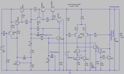
Yes! There is a MKIII version (I really can't help myself). I have now gone a bit nutty, having added a series pre-regulator.
Have fun 😀!
Attachments
I don't think my breadboarding skills could manage mk111.
If the pre-reg is that good, then how much of that improvement could be got from a 317?
I see you have reduced the CCS cascode now that dissipation is way down, since it does not have to cope with 105V on the input.
What voltage across the CCS gets best performance from it?
If the pre-reg is that good, then how much of that improvement could be got from a 317?
I see you have reduced the CCS cascode now that dissipation is way down, since it does not have to cope with 105V on the input.
What voltage across the CCS gets best performance from it?
AndrewT said:I don't think my breadboarding skills could manage mk111.
If the pre-reg is that good, then how much of that improvement could be got from a 317?
I see you have reduced the CCS cascode now that dissipation is way down, since it does not have to cope with 105V on the input.
What voltage across the CCS gets best performance from it?
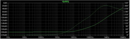
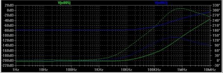
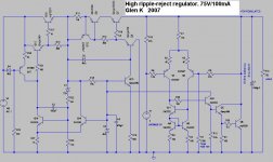
I have made at MK4 version, with a slight improvement to the series pass pre regulator, which now gives a few dB better ripple rejection with crappy MJE34(5)0 trannies. The pre reg simulates about 80dB ripple rejection out to 20kHz.
Look at the plot attached. The blue trace is for the output of the pre reg, the green trace is the 75V output. Haven't compared this with an LM317 datasheet but I'm guessing It's probably about 10 to 20dB better.
I'm running Q7 with about 5V Vce. If I lower it to a volt or so the ripple rejection decreases by a (minor) few dB, probably due to Cob going through the roof at low Vce. Anything above 5V makes no difference.
Attachments

Maybe some of you can help. I found a transformer for my monster output stage but intead of my planned 45v transformer it's a 54v. It's a beautiful 2.4KVA unit but I end up with about 75v rails instead of 65. So do any of you know of a good way to drop the rail voltages by about 10V? I was thinking maybe a simple high current regulator but am not so good at figuring out the details.
dinu said:Maybe some of you can help. I found a transformer for my monster output stage but intead of my planned 45v transformer it's a 54v. It's a beautiful 2.4KVA unit but I end up with about 75v rails instead of 65. So do any of you know of a good way to drop the rail voltages by about 10V? I was thinking maybe a simple high current regulator but am not so good at figuring out the details.
Regulator approaches can be made to work, but there will be a price in dissipation and complexity. A side benefit is, of course, potentially cleaner rails.
Is the transformer a toroid? Does it have split secondaries? You can play games with toroids where you can wind additional "bucking" windings on them to effectively subtract some volts, either from each of the split secondaries, or from the primary. Fooling with the primary might not be UL politically correct.
I suppose you could also get a 6 or 12 V filament transformer and put its secondary voltage in series with the primary of the main transformer so that it bucks it down by 10-15%. Again, I'm not certain of the UL political correctness of doing this.
Cheers,
Bob
http://plitron.com/shopping/shopexd.asp?id=624
It's a Plitron surplus transformer. I intended to use the full 240v primary in series and thus get 55v on each full secondary. It's potted already so no additional windings are possible. My original intent was to use a large fet like an Irf9240 as a regulator fed a reference from a zener stack but I think the constant dissipation would create alot of heat.
I designed my output stage to run on +-65v rails and draw about 170ma per complementary pair (9 pairs total). Finally, I may be able to just drop the bias current a bit if nothing else works.
This excercise does make me wonder why, in the interest of uncompromised performanance, no-one ever regulates the power supply to the output stage.
I wonder if that one would not make a lovely technical balanced power unit...
http://www.equitech.com/index.html
😉
http://www.equitech.com/index.html
😉
Ok.
IF, and only IF, you have enough galvanic insulation among the secondaries (ask plitron about this), you´ll be able to obtain 23.5vac-ct-23.5vac at the secondaries connecting one of them (ct-60vac - only half of the secondary) in series with 110+110vac in primary and feeding the total series winding (110+110+60) on 110vac from mains.
This configuration, if you use one half winding from primary will limit the total power on primary by the capacity of the secondary wire (4.15A) at 450VA.
If you need more power, just put more secondaries in parallel, adding 4,15A to the current capacity and, therefore, adding more 450VA to the available power per secondary added in parallel.
Remeber, these secondaries (the 60-ct-60 wiring used in series with the primaries) MUST be isolated from the real secondaries and MUST have the correct galvanic insulation from the other secondaries (since it is a 120vac winding, I suppose it is true for this transformer, but I think you have to ask the guys at Plitron).
Best regards
awesome idea.
Never thought of that but it would work great. I can use one of the secondaries as a primary and still have 4 secondaries available for whatever I need. I'll check with Plitron and let you guys know how it pans out.
Thanks.
Never thought of that but it would work great. I can use one of the secondaries as a primary and still have 4 secondaries available for whatever I need. I'll check with Plitron and let you guys know how it pans out.
Thanks.
Well bad news.
Plitron says that the secondaries were all wound simultaneously with no additional insulation between then. I can however, use the secondaries as primaries and connect them in series. I would the have a 45-0-45 by using the 115 primaries as center tapped secondaries. The problem then becomes that I can't distribute the load to individual bridges and get that nice channel separation. Dilema.
Still, I would like any input that some of you may have on whether or not it's reasonable to regulate output stage rails. If so, then how?
Is your design poor regarding power supply rejection?
If not, there is big no reason to split the windings.
Another possibility is to regulate it using switching step-down converters. There are low power losses, but, as in any regulated design, you have to deal with feedback nodes and stability questions.
best regards,
If not, there is big no reason to split the windings.
Another possibility is to regulate it using switching step-down converters. There are low power losses, but, as in any regulated design, you have to deal with feedback nodes and stability questions.
best regards,
The psu rejection is pretty good. It uses paralleled Irf240's and 9240's as complementary pairs. They are driven by a cascoded front end with a separate and well filtered supply using a separate torroid also from Plitron. There are 9 pairs of matched output devices per channel.
My further probing arises from my observation that high end audio amps often accept drastically deminishing returns in the interest of minimal increases in performance. I see diy'ers as well as manufacturers go to really astonishing lengths for what are sometimes almost inperceptible performance gains. Individuals on these forums sometimes employ Voodoo-like methods to get, what they hope will be, a little bit better sound. There's certainly no lack of determination, and practicality in this field has long ago died an unceremonious death. I gladly accept that myself and admit that there is nothing practical about my efforts. So finally, if there is any benefit to be gained from using a better filtered output supply, I'm surprised that's not a hot topic. It certainly would offer a more fruitful avenue than .9999999999% pure silver wires or $300 speaker spikes or $5,000 interconnects. Have any of you read the Blowtorch thread? SOLID BILLET ALUMINUM CHASSIS FOR $3,000!! Do any of these people realize that milling a part from a solid block has the structural value of soap carving?
Sorry. I have to stop now before I get carried away. Maybe a high current regulator has some merit.
It's reasonable, and quite sure many people do. Actually, not fixed voltage regulators but things like simple followers with RC- or RLC-filtered bases/gates (aka ripple eaters, gyrators, cap multipliers etc), thus not suffering too much from losses. If one designs the rail's "center tap" to be after the regulation, not at the xformer, one can get away with cheap high power N-ch. MOSFETS. Also, a "trick" not widely known is to add a series LC right after the bridge (across the reservoir cap) tuned to the fundamental (100Hz or 120Hz), which cleans up a lot of that fundamental and makes the filtering easier (at the cost of higher stress on xformer and rectifiers).dinu said:Still, I would like any input that some of you may have on whether or not it's reasonable to regulate output stage rails. If so, then how?
- Klaus
I`m working in the Hydro-power plant and I measured some interesting data few days ago...
Actually, in the 220VAC/50Hz mains, we measured 11% of second harmonic!
Actually, in the 220VAC/50Hz mains, we measured 11% of second harmonic!
dinu said:http://plitron.com/shopping/shopexd.asp?id=624
It's a Plitron surplus transformer. I intended to use the full 240v primary in series and thus get 55v on each full secondary. It's potted already so no additional windings are possible. My original intent was to use a large fet like an Irf9240 as a regulator fed a reference from a zener stack but I think the constant dissipation would create alot of heat.
I designed my output stage to run on +-65v rails and draw about 170ma per complementary pair (9 pairs total). Finally, I may be able to just drop the bias current a bit if nothing else works.
This excercise does make me wonder why, in the interest of uncompromised performanance, no-one ever regulates the power supply to the output stage.
I think that you would be waaayyyyyyy better off just redesigning your output stage to run on +/-75V rails.
Cheers,
Glen
Need advice...
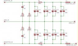
Hi all,
I need your opinion about this power supply. It consists of a 40-0-40V 400VA toroidal trafo with one metal bridge rectifier for both rails,each rail will have 4 x 10000uf/80v caps. The 3R3 resistors in each rail will have 40 turns of 1mm enameled wire on them (as a coil). It's going to feed a 150/300W 8/4ohm Class AB amplifier. Do I have to make some changes, according to your opinion-expirience?
Thanasis.
Attachments
- Status
- Not open for further replies.
- Home
- Amplifiers
- Solid State
- Bob Cordell Interview: Power Supplies