is GP where you insert your loop gain probe?
Or, do you want to show us where you insert the probe?
Or, do you want to show us where you insert the probe?
[snip]Yes, see below.
Cheers,
E.
[snip].
Edmond, I noticed a factor of two difference in THD20 depending on whether the input filter is present or not. Do you know the reason for that?
jan didden
</p>Hi YWN,
Probably you are confusing the open loop gain with global NFB loop gain. Indeed, the terminology is a little confusing. In case of the former, there isn't a loop at all, as it is broken. At very low frequencies (<0.1Hz), indeed, the phase is zero. In case of the latter, it's correct that phase of the loop (at point GP, see below) is +90 degrees and at very low frequencies 180 degrees. Notice that I'm talking about loop-gain. This differs from the so called return-ratio in that the loop-gain = minus return-ratio. So, if we are talking about the return-ratio, then the phase will be -90 degrees. As you see, one more potential source of confusion (and debate!)
Hi Edmond, I'm pretty sure I'm not confusing the loop gain with the open loop gain, but otherwise this stuff is quickly going way over my head. I was simply asking where is the 0.1Hz or smthing pole coming from. Now that I see the schematic, I really don't get it. If you could post the method used simulate the TTPC gain phase (break point place and method, gain/phase probe used, etc...) then maybe I could figure it out. Thanks for your help, I'm only trying to get an apple to apple comparison in your post #3198.
Edmond, I noticed a factor of two difference in THD20 depending on whether the input filter is present or not. Do you know the reason for that?
jan didden
Hi Jan,
It's the resistor at the non-inverting input together with the base current that spoils the THD figure a little bit.
Douglas Self (and may others, I suppose) has written an article about this phenomenon in EW/WW.
Cheers,
E.
Phase shift.
Do you really think I'm that stupid to not take that into account?
Hi Edmond,
[snip]
If you could post the method used simulate the TTPC gain phase (break point place and method, gain/phase probe used, etc...) then maybe I could figure it out. Thanks for your help, I'm only trying to get an apple to apple comparison in your post #3198.
Hi YWN,
Here it is. Simply feed the input signal as shown below and observe V(out)/V(in). that's all.
Good luck.
E.
Attachments
Save strong words, Edmond. Phase shift of RC HP and LP matters in simulation, though it does not matter in a real life measurement.
 Do you really think I'm that stupid to not know that?
Anyhow, this case has nothing to do with phase.
Hi YWN,
Here it is. Simply feed the input signal as shown below and observe V(out)/V(in). that's all.
Hi Edmond, thanks, I hate being a PITA, I see you changed the schematic re: your previous post, with a 1E6F cap instead of 1mF cap, was the 1mF cap the reason for the 0.1Hz or smthing pole in the loop gain?
I guess the signal is a voltage Vin, but where to feed to reproduce your results? Between IN and OUT, right? Are you not using a gain/phase probe (GP)?
Hi Edmond, thanks, I hate being a PITA, I see you changed the schematic re: your previous post, with a 1E6F cap instead of 1mF cap, was the 1mF cap the reason for the 0.1Hz or smthing pole in the loop gain?
1e6F is what I'm using in simulations. In real live however, it's hard to find a cap that large, so I've replaced it by 1mF for real applications.
The sudden phase transition at about 100Hz has no (or only a weak) relation with these caps.
I guess the signal is a voltage Vin, but where to feed to reproduce your results? Between IN and OUT, right?
That's right.
Are you not using a gain/phase probe (GP)?
Actually, this is a simplified 'gain probe'. In this case, this method is reasonable accurate, because the impedance at node 'IN' (about 2k3) is much, much higher than the output impedance. The DC working point is preserved by the addition of R35.
(If the impedances are of the same order, you must use a Middlebrook or Tian gain probe. Whenever allowed, I'm not using such a gain probe, as it is a PITA with MicroCap)
Cheers,
E.
The sudden phase transition at about 100Hz has no (or only a weak) relation with these caps.
Actually, this is a simplified 'gain probe'. In this case, this method is reasonable accurate, because the impedance at node 'IN' (about 2k3) is much, much higher than the output impedance. The DC working point is preserved by the addition of R35.
Thanks, then I am at lost again about the LF pole. Something is not right, but I don't know what.
But isn't the connection through Vin enough to keep the right bias? Why do you need R35?
If I am to ignore this LF pole, if the loop gain is the same (hence the THD is the same), and if the phase margin is the same, then I would say there is absolutely no reason to prefer one over the other in your post #3198. The phase dip and the corresponding oveshoot in the time domain has absolutely no effect on the sound quality, even without the input RF filter pole (which is otherwise mandatory and limits the closed loop BW to 200KHz or smthing).
Thanks, then I am at lost again about the LF pole. Something is not right, but I don't know what.
But isn't the connection through Vin enough to keep the right bias? Why do you need R35?
As I said already, R35 is absolute necessary to maintain a proper DC operating point.
The global loop gain is (about) the same. That doesn't automatically mean that the THD is also the same. There are more loops and more factors involved.If I am to ignore this LF pole, if the loop gain is the same (hence the THD is the same),
THD20 of the ETMC amp is at least five times lower than the TTPC amp.
and if the phase margin is the same, then I would say there is absolutely no reason to prefer one over the other in your post #3198. The phase dip and the corresponding overshoot in the time domain has absolutely no effect on the sound quality,
How do you know that? Things are not always that simple.
even without the input RF filter pole (which is otherwise mandatory and limits the closed loop BW to 200KHz or smthing).
You will need an input filter anyhow, but some people advocate to use a quite hefty input filter to make the overshoot invisible. You can do this by increasing the C, but not every pre-amp will appreciate that, or you can increase R, which means more noise and/or more distortion, at least with this particular design.
Last but not least, I think I did my utmost best to explain the ins and outs of this amp, but apparently, explaining simple, obvious or fundamental matters is not my forte. So if there are any unanswered questions left, I hope that somebody else will answer them.
Cheers,
E.
The global loop gain is (about) the same. That doesn't automatically mean that the THD is also the same. There are more loops and more factors involved.
THD20 of the ETMC amp is at least five times lower than the TTPC amp.
Thanks again, I will look further in the schematic(s) and details; but otherwise, when making a choice, as you also didn't mention up front the circuit topology for each plot, I wouldn't think it is possible to figure out the presence of "more loops and more factors involved", and a x5 times lower THD, from the simple gain-phase plots you posted in #3198.
If multiloops are involved, then I think the stability of an amp may depend on much more than global loop gain/phase margin, be it with a phase dip or not.
...BTW2, Bob, do you think it's possible to get rid of that ugly phase dip (and overshoot), by inserting an all-pass filter into the global NFB network?
Cheers,
E.
I'm afraid that appealing to Bob or anybody else won't help when you're looking straight at the fundamental limits of negative feedback
minimum phase is required for maximum applied feedback - all pass "phase correction" is not minimum phase
I keep pointing to B.J. Lurie's work for a reason - it is unusual in showing how to apply Bode integrals to feedback, illustrating the limits
the phase dip is an explicit cost of using higher order gain slope - can't be avoided
higher order loop gain slopes enable more audio frequency loop gain - because the "area" of frequency*ln|F| of the negative feedback region is fixed by the stability limit - so having it "poke up" higher in the audio frequency range implies getting lower faster at higher frequencies to meet the gain phase margins
Bode integrals are useful tools - at a high level they tell you what can/cannot be done with negative feedback
http://trs-new.jpl.nasa.gov/dspace/bitstream/2014/19495/1/98-0905.pdf
Lurie's site is gone but lives on in the WayBack Machine:
Classical Feedback Control, Chapter 4: Shaping the Loop Frequency Response
Mitchell covers some of the same territory:
Dr Richard Mitchell's Selected Research Papers and Presentations
all-pass filter
Hi JCX,
I was afraid of that too. I've tried several things to improve the transmission function without avail. As my knowledge of filter theory has (somewhat) faded away, I was hoping that some expert in this field might show up with a solution. So this seems to be not possible. Thanks for enlighten me and for the references.
Cheers,
E.
I'm afraid that appealing to Bob or anybody else won't help when you're looking straight at the fundamental limits of negative feedback ..............
Hi JCX,
I was afraid of that too. I've tried several things to improve the transmission function without avail. As my knowledge of filter theory has (somewhat) faded away, I was hoping that some expert in this field might show up with a solution. So this seems to be not possible. Thanks for enlighten me and for the references.
Cheers,
E.
I'm afraid that appealing to Bob or anybody else won't help when you're looking straight at the fundamental limits of negative feedback
minimum phase is required for maximum applied feedback - all pass "phase correction" is not minimum phase
I keep pointing to B.J. Lurie's work for a reason - it is unusual in showing how to apply Bode integrals to feedback, illustrating the limits
the phase dip is an explicit cost of using higher order gain slope - can't be avoided
higher order loop gain slopes enable more audio frequency loop gain - because the "area" of frequency*ln|F| of the negative feedback region is fixed by the stability limit - so having it "poke up" higher in the audio frequency range implies getting lower faster at higher frequencies to meet the gain phase margins
Bode integrals are useful tools - at a high level they tell you what can/cannot be done with negative feedback
http://trs-new.jpl.nasa.gov/dspace/bitstream/2014/19495/1/98-0905.pdf
Lurie's site is gone but lives on in the WayBack Machine:
Classical Feedback Control, Chapter 4: Shaping the Loop Frequency Response
Mitchell covers some of the same territory:
Dr Richard Mitchell's Selected Research Papers and Presentations
Hi JCX,
This is a very good response, and is quite educational. I was also thinking that the introduction of an all-pass might not be a good thing (it introduces phase lag into the loop without corresponding rolloff), but would not have been able to come up with such a detailed response.
Cheers,
Bob
TMC shunt compensation
Hi Bob,
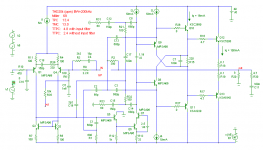
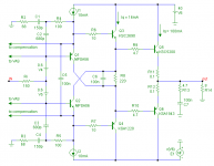
As you already know, I fully agree with above points. But.... loading the collector of the VAS with a (light) shunt compensation network compromises or might compromise the slew rate and increases the distortion. The schematic in post 3220 shows an arrangement which overcomes this unwanted side effect. See below for a detailed snippet. The crux is that the shunt compensation has also been 'TMCized' by means of C2 and R4, respectively C3 and R5. As a result, the VAS loading is only effective at HF, while at AF the loading is far less, hence the slew rate becomes far better and the distortion is about halved.
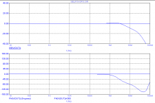
But that's not all. This arrangement addresses one more issue: a diamond driver with bootstrapped collectors of the pre-driver is rather prone to instabilities, in particular when it is driven by a not so low impedance of the signal source. The second picture shows what happens without compensation and Ri is (only!) 150 Ohms, The peaking at ~15MHz predicts nothing but trouble. The third (right) picture shows the response with TMC shunt compensation. Now, that ugly peak has vanished.
Cheers,
E.
Hi Edmond,
I have also seen that taking the compensation feedback from the pre-driver is dangerous to the stability of the compensation loop, and have also noted the need for the light shunt compensation at the collector of the VAS. This shunt compensation makes the VAS act a bit more like it does when the Miller feedback is taken from the VAS, with the Miller capacitor providing some loading and controlling the gain bandwidth of the compensation loop. Taking the compensation from the pre-driver unloads the VAS, but sometimes by too much.
Taking the compensation feedback from the pre-driver can be especially dangerous when the VAS is a Darlinton-cascode, as the VAS self-loading is less and there are more transistors in the compensation loop, adding excess phase.
Cheers,
Bob
Hi Bob,
As you already know, I fully agree with above points. But.... loading the collector of the VAS with a (light) shunt compensation network compromises or might compromise the slew rate and increases the distortion. The schematic in post 3220 shows an arrangement which overcomes this unwanted side effect. See below for a detailed snippet. The crux is that the shunt compensation has also been 'TMCized' by means of C2 and R4, respectively C3 and R5. As a result, the VAS loading is only effective at HF, while at AF the loading is far less, hence the slew rate becomes far better and the distortion is about halved.
But that's not all. This arrangement addresses one more issue: a diamond driver with bootstrapped collectors of the pre-driver is rather prone to instabilities, in particular when it is driven by a not so low impedance of the signal source. The second picture shows what happens without compensation and Ri is (only!) 150 Ohms, The peaking at ~15MHz predicts nothing but trouble. The third (right) picture shows the response with TMC shunt compensation. Now, that ugly peak has vanished.
Cheers,
E.
Attachments

Hi
Many talk in this post about Overshoot depending on the topology, I did not understand in what condition (unconditional instability?).
I also have a overshoot with load 8//2u, I wonder if really this heavy load is required ???
BTW
Sorry Edmond if my post is a little off topic.
Many talk in this post about Overshoot depending on the topology, I did not understand in what condition (unconditional instability?).
I also have a overshoot with load 8//2u, I wonder if really this heavy load is required ???
BTW
Sorry Edmond if my post is a little off topic.
Hi Bob,
As you already know, I fully agree with above points. But.... loading the collector of the VAS with a (light) shunt compensation network compromises or might compromise the slew rate and increases the distortion. The schematic in post 3220 shows an arrangement which overcomes this unwanted side effect. See below for a detailed snippet. The crux is that the shunt compensation has also been 'TMCized' by means of C2 and R4, respectively C3 and R5. As a result, the VAS loading is only effective at HF, while at AF the loading is far less, hence the slew rate becomes far better and the distortion is about halved.
But that's not all. This arrangement addresses one more issue: a diamond driver with bootstrapped collectors of the pre-driver is rather prone to instabilities, in particular when it is driven by a not so low impedance of the signal source. The second picture shows what happens without compensation and Ri is (only!) 150 Ohms, The peaking at ~15MHz predicts nothing but trouble. The third (right) picture shows the response with TMC shunt compensation. Now, that ugly peak has vanished.
Cheers,
E.
Hi Edmond,
Very clever!
BTW, wrt the peak with the bootstrapped diamond buffer, I have some feeling that the speedup capacitor C6 exacerbates it by closing a positive feedback loop at HF around each cascaded EF pair. Without C6, each predriver collector just gets a feedforward bootstrapped signal from the other (somewhat independent) side. Without C6, and with some resistance in series with each predriver base, I think the peaking is mitigated. Just a thought.
Cheers,
Bob
- Home
- Amplifiers
- Solid State
- Bob Cordell Interview: Negative Feedback