G.Kleinschmidt said:Hmm. I guess it would be reduced.
Glen what is you thoughts/assessment of the odd harmonics generated on the supply lines with Class B or Class A/B stages (even overbiased) ?
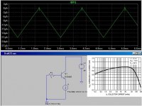
Truth is to me (from what I can make out) is a linear output transfer function (whether accomplished with extensive local NFB - hawkesford/cordell or current dumping etc or whatever you call it) is not the be all and end all of amplifiers. A scope shows me that on the rails.
Amps do not have infinite PSRR and people confuse a.c. PSRR with d.c. PSRR. Two different animals. This is blatent from the way people do simulations.
Would like your take on it as a pragmatist.
Thanks
All the best
Kevin
Fanuc said:[snip]Truth is to me (from what I can make out) is a linear output transfer function (whether accomplished with extensive local NFB - hawkesford/cordell or current dumping etc or whatever you call it) is not the be all and end all of amplifiers. A scope shows me that on the rails.[snip]Kevin
Kevin,
Not wanting to pre-empt Glen's reply, but the modulation you see on the rails should make no difference whether the amp is high nfb or EC or current dumping or whatever. Only the toplogy (class AB/B or class B) should make a difference. Correct?
Jan Didden
Yup Jan. You taught me that one. If you use less capacitance on the rectifiers/rails you can get predominately very low level harmomics (easy to reject.) plus with a regulated PSU for the output stage the ripple current rating of the smoother/reservoir caps does not need to match the output current demands.
A couple of questions Jan (with the new network anaylzer 🙂
I was seriously dissappointed with an AP system model 2700. The two most important tests for power amps IMO are (a) phase margin stability - network anayliser (b) FFT (spectrum) analysis of the distortion spectra. (even more so nowadays.). Glad I never bought one when I had the money.
1, You tried Scott Wurcer's mod in using a neutrulisation capacitor with _your_ (ie. '95 type) PCB layout with the AD797 ?
He adds an additional cap to deduct from the internal miller cap (series connection) and measured outragous Zouts at 100Khz etc. One of the graphs on the AD797 datasheet shows ruler flat Zout upto hundred's of Khz's with that cap. I will start with what is recommended in that datasheet for doing this.
I will change the load resistor for the lm329 or lm4040 (as I need) to a CCS so it can withstand a short circuit when the thyristor activates measuring too much dc offset/overload.
I will be in touch in the next few days. Sorry for the typo's had a few beers. Tunnel vision nah double vision 🙂
Kevin
Fanuc said:Yup Jan. You taught me that one. If you use less capacitance on the rectifiers/rails you can get predominately very low level harmomics (easy to reject.) plus with a regulated PSU for the output stage the ripple current rating of the smoother/reservoir caps does not need to match the output current demands.
A couple of questions Jan (with the new network anaylzer 🙂
I was seriously dissappointed with an AP system model 2700. The two most important tests for power amps IMO are (a) phase margin stability - network anayliser (b) FFT (spectrum) analysis of the distortion spectra. (even more so nowadays.). Glad I never bought one when I had the money.
1, You tried Scott Wurcer's mod in using a neutrulisation capacitor with _your_ (ie. '95 type) PCB layout with the AD797 ?
He adds an additional cap to deduct from the internal miller cap (series connection) and measured outragous Zouts at 100Khz etc. One of the graphs on the AD797 datasheet shows ruler flat Zout upto hundred's of Khz's with that cap. I will start with what is recommended in that datasheet for doing this.
I will change the load resistor for the lm329 or lm4040 (as I need) to a CCS so it can withstand a short circuit when the thyristor activates measuring too much dc offset/overload.
I will be in touch in the next few days. Sorry for the typo's had a few beers. Tunnel vision nah double vision 🙂
Kevin
I'll wait for your vision to stabilize 😉
BTW Scott Wurcer's 797 concept was discussed in 'John Curl's Blowtorch' thread, you may want to read up on that. Or ask Scott - he is very approachable.
Jan Didden
janneman said:
I'll wait for your vision to stabilize 😉
BTW Scott Wurcer's 797 concept was discussed in 'John Curl's Blowtorch' thread, you may want to read up on that. Or ask Scott - he is very approachable.
Jan Didden
I tried it in the Jung super-regulator and it worked there out to 100kHz at least. IIRC it was 10-6 Ohms flat.
Fanuc said:
I was seriously dissappointed with an AP system model 2700. The two most important tests for power amps IMO are (a) phase margin stability - network anayliser (b) FFT (spectrum) analysis of the distortion spectra. (even more so nowadays.). Glad I never bought one when I had the money.
Kevin
Hi Kevin,
These are very good points. The spectral analysis issue cannot be stressed enough. However, even with that, many THD-20 measurements get cut off at 80 kHz, so upper harmonics are not adequately accounted for. 19+20 kHz CCIF IM with spectral analysis is far superior, since it reveals in-band consequences of high-order distortion products.
Amplifier stability under ALL conditions is also very important, noy just phase margin under quiescent conditions. Amplifiers often sound different because they MISBEHAVE differently, and misbehavior often does not show up under ordinary lab testing.
Cheers,
Bob
andy_c said:It looks like TPC the way I drew it 🙂. BTW, thanks for posting that D. Self reference. I have that book but haven't read it nearly as closely as his power amp book. I'm going to reduce the resistor in my input LPF I think.
No worries. BTW, I think that lowering that resistor value is a good idea. Self's better measurements were made with 'B' grade devices and the distortion was still significant.
In chapter 4, after addressing the PSRR issue Self identifies the non-linear base currents accompanying the audio input signal as a remaining source of 2nd harmonic distortion.
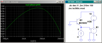
I’m not sure how reliably this can be predicted in SPICE. I ran the basic sim attached with a bunch of transistors in the LTspice library to see how well beta non-linearity is simulated and it seems, in all cases so far, not very.
The current source is set to deliver a 0-to-10mA triangle wave emitter current for the BJT under test and the base current through R1 is plotted.
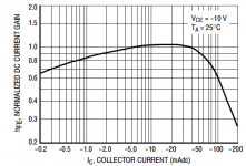
With the small-signal devices I just get perfectly linear base current plots for 0-10mA Ie range (regardless of Vce), which doesn't exactly match the hfe graphs in the datasheets!
Attachments
Hi Glen,
I have a writeup on my web pages of how SPICE handles beta variation with IC here. The parameters ISE and NE handle the decrease in beta at low collector currents. IKF and the undocumented NK handle the beta decrease at high collector currents.
Below is a parametric plot of beta vs. IC of the BC560C model I use in my sim. To get a parametric plot, just left-click on the x-axis, and in "quantity plotted", enter the formula. A minus sign is required for IC(Q1) on the x-axis for a log plot with a PNP. Here's the model:
.MODEL BC560c PNP
+ IS = 2.24183E-14
+ NF = 0.996496
+ ISE = 3.0e-12
+ NE = 2
+ BF = 550
+ IKF = 0.211766
+ VAF = 161.939
+ NR = 0.993
+ ISC = 4.7863E-15
+ NC = 0.996
+ BR = 12.1807
+ IKR = 0.3423
+ VAR = 123.229
+ RB = 167.033
+ IRB = 7.079458E-05
+ RBM = 1.12256
+ RE = 0.036
+ RC = 0.79
+ XTB = 1.65
+ EG = 1.1737
+ XTI = 3
+ CJE = 1.87E-11
+ VJE = 0.732
+ MJE = 0.33
+ CJC = 6.16E-12
+ VJC = 0.395
+ MJC = 0.251
+ XCJC = 0.6192
+ FC = 0.5
+ TF = 518.15E-12
+ XTF = 10
+ VTF = 10
+ ITF = 1
+ TR = 10.000E-9
Here's the plot. It's pretty close at low currents. I tweaked a Fairchild model to get this result. I didn't try to match what's going on at high currents, as it doesn't get used up there.
Attachments
Bob Cordell said:
Hi Kevin,
These are very good points. The spectral analysis issue cannot be stressed enough. However, even with that, many THD-20 measurements get cut off at 80 kHz, so upper harmonics are not adequately accounted for. 19+20 kHz CCIF IM with spectral analysis is far superior, since it reveals in-band consequences of high-order distortion products.
Amplifier stability under ALL conditions is also very important, noy just phase margin under quiescent conditions. Amplifiers often sound different because they MISBEHAVE differently, and misbehavior often does not show up under ordinary lab testing.
Cheers,
Bob
Agree entirely Bob. Next question is can we do these tests at reasonably low cost? Most network analyzers ain't cheap, even to rent for a month. It startles me sometimes that power amp designers do compensation techniques and say it's stable without actually measuring it in circuit!! Spice goes so far but is not adequate. I can't do hybrid PI modelling etc of Q's and circuits - that's out of my depth.
I beleive that FFT can be done by some very good PC based soundcards etc. This has probably been covered to death, but I will have a look into it if some links are provided.
Thanks
Kevin
andy_c said:Here's the simulation in case you want to run it. I've included the .plt file so the plot comes up automatically. But apparently it autoscales, so you'll need to reset the min and max values of the x-axis.
Thanks Andy 🙂
This stuff is exactly what I was looking up now.
G.Kleinschmidt said:In chapter 4........
Typo correction -chapter 24; "Power amplifier input currents and their troubles" (Self on Audio).
Bob Cordell said:
Hi Kevin,
These are very good points. The spectral analysis issue cannot be stressed enough. However, even with that, many THD-20 measurements get cut off at 80 kHz, so upper harmonics are not adequately accounted for. 19+20 kHz CCIF IM with spectral analysis is far superior, since it reveals in-band consequences of high-order distortion products.
Amplifier stability under ALL conditions is also very important, noy just phase margin under quiescent conditions. Amplifiers often sound different because they MISBEHAVE differently, and misbehavior often does not show up under ordinary lab testing.
Cheers,
Bob
What are ALL these conditions (other than clipping):
reactive load, output level, power dissipation, ..others.
Do you have some misbehavoirs examples?
Thanks
JPV
Fanuc said:
Agree entirely Bob. Next question is can we do these tests at reasonably low cost? Most network analyzers ain't cheap, even to rent for a month. It startles me sometimes that power amp designers do compensation techniques and say it's stable without actually measuring it in circuit!! Spice goes so far but is not adequate. I can't do hybrid PI modelling etc of Q's and circuits - that's out of my depth.
I beleive that FFT can be done by some very good PC based soundcards etc. This has probably been covered to death, but I will have a look into it if some links are provided.
Thanks
Kevin
Hi Kevin,
Many of these tests can be done with conventional test equipment with perhaps some home-built electronic accessories. You can do an awful lot with an audio generator, wideband scope (>100 MHz), and a soundcard-based spectrum analysis tool, perhaps with a home-built I/O adapter circuit to buffer inputs and outputs and do some scaling. An AC voltmeter is also important to have.
19+20 kHz CCIF can be done with two oscillators feeding a low-distortion summer, followed by a PC-based spectrum analyzer. In some cases a home-built distortion magnifier (as described on my web site) can help add an extra 20 dB or 40 dB of dynamic range to the spectrum analysis or to THD analysis.
Less often used tests involve some imagination. Never overlook low-frequency THD at 50 Hz or so. Check square wave response into difficult loads at high power levels to see signs of ringing or bursts of oscillation.
Sometimes back-driving the amplifier with another amplifier through an 8-ohm power resistor can provoke protection and other forms of "misbehavior".
How an amplifier clips at different frequencies can also relate to sound differences that may occur between different amplifiers.
This is just a short list of things to try. The main thing is to use your imagination, and the resulting tests often do not require expensive test equipment.
Some tests, of course, carry with them the risk of blowing up the amplifier. Sometimes a tone-burst generator can be used to minimize the duration of the stressful test. Example: two cycles of 20 kHz at full power into a 2-ohm load.
Cheers,
Bob
Over in the Otala thread, somebody brought up the discussion that occurred earlier in this thread about the Baxandall article in Wireless World concerning the effect of feedback on individual components of harmonic distortion. This got me thinking about it a bit more.
What was bugging me was the seemingly depressing nature of Baxandall's results - namely the appearance of high-order harmonics at uncomfortably high levels in the closed-loop amplifier. Baxandall's graph for the FET case is attached below. This shows the distortion components vs. feedback, in which it's assumed the open-loop amplifier has only second-order distortion. The dashed lines are the calculated data and the solid lines are the measurement.
One thing to notice is that the assumed distortion of the open-loop amplifier is quite high - almost 10 percent. It's pretty well known that it's bad practice to use feedback to cover up large amounts of distortion in the open-loop amplifier. This brings up the question of what Baxandall's graph would look like in the case of a proper design for which the open-loop distortion were much lower. Let's assume the open-loop distortion is a more reasonable value such as, say, 0.1 percent. This corresponds to a reduction in open-loop distortion of a bit less than 40 dB. For simplicity, I'll assume it's exactly 40 dB from Baxandall's original assumption. Also, I'll only treat the case for which the open-loop amplifier has only second-harmonic distortion. The case where all harmonics are allowable in the open-loop amplifier becomes intractable.
Let's consider a circuit having output y and input x for which the nonlinearity is static, whose distortion is second-harmonic only, and whose DC offset is zero. Here x or y can be either voltage or current. The input-output relationship of this circuit looks like this:
y = f(x) = a1 * x + a2 * x2
Here a1 is the small-signal gain and a2 is a number that determines the amplitude of the second-order harmonic distortion component. If we wish to linearize this thing while keeping its small-signal gain the same, there's only one thing we can do - reduce the absolute value of a2. But we can think of this in another way. Suppose the linearized function is called g(x). Further suppose that we get g(x) by putting an attenuator of value K ahead of the nonlinear circuit f(x) above, then boost its output by K. Mathematically, this is:
g(x) = K * f(x / K)
It's easy to show that the small-signal gain has not changed, but the distortion has been reduced. This is because the attenuation and gain K cancel each other out in terms of the small-signal gain. However, the attenuator has reduced the excursion of the input signal into the nonlinearity and thus reduced distortion.
So we can say there's an equivalency here - dropping the signal level at the nonlinearity is completely equivalent to linearization of the circuit in this simple second-order case. This allows us to exploit a key relationship for weakly nonlinear circuits. For such circuits, if we drop the input signal by c dB, the fundamental component of the output will also drop by c dB. The absolute level of the second harmonic component at the output will drop by 2c dB, the third by 3c dB, the fourth by 4c dB, the fifth by 5c dB, the sixth by 6c dB, and the seventh by 7c dB. Stated another way, the second harmonic relative to the fundamental will drop by c dB, the third by 2c dB, the fourth by 3c dB, the fifth by 4c dB, the sixth by 5c dB, and the seventh by 6c dB.
Now we can look at the effect of reducing the open-loop distortion from 10 percent to 0.1 percent. It should be clear that this is equivalent to K = 100 above. For K = 100, the fundamental component of the signal at the output of the nonlinearity drops by 40 dB, while the absolute level of the second harmonic drops by 80 dB. Thus the distortion percentage of the open-loop amplifier improves by 40 dB or 100 times, which is the desired amount. Now we can compute the changes in level for the other harmonics in the closed-loop amplifier using the relationship above. The numbers below are all relative to the fundamental, the same as Baxandall's graphs portray.
2nd harmonic distortion drops by 40 dB
3rd harmonic distortion drops by 80 dB
4th harmonic distortion drops by 120 dB
5th harmonic distortion drops by 160 dB
...and so on. The numbers above would be the amount you'd shift the data down for each harmonic component in Baxandall's graph below. We see that we got a 40 dB improvement for the closed-loop 2nd harmonic distortion for a 40 dB improvement in the open-loop 2nd harmonic distortion. However, we are getting a very disproportionate improvement in the higher harmonics of the closed-loop amplifier here. This is encouraging. It demonstrates the importance of keeping the open-loop amplifier linear.
Of course, in the real world, it won't really be possible to linearize the open-loop amplifier without introducing open-loop harmonics of order higher than 2. This makes the real-world situation much more complex than the greatly simplified analysis above. But it does demonstrate one thing. For Baxandall to show the high-order harmonics of the closed-loop amplifier at non-trivial levels, he had to assume very high distortion of the open-loop amplifier.
Attachments

andy_c said:Over in the Otala thread, somebody brought up the discussion that occurred earlier in this thread about the Baxandall article in Wireless World concerning the effect of feedback on individual components of harmonic distortion. This got me thinking about it a bit more.
What was bugging me was the seemingly depressing nature of Baxandall's results - namely the appearance of high-order harmonics at uncomfortably high levels in the closed-loop amplifier. Baxandall's graph for the FET case is attached below. This shows the distortion components vs. feedback, in which it's assumed the open-loop amplifier has only second-order distortion. The dashed lines are the calculated data and the solid lines are the measurement.
One thing to notice is that the assumed distortion of the open-loop amplifier is quite high - almost 10 percent. It's pretty well known that it's bad practice to use feedback to cover up large amounts of distortion in the open-loop amplifier. This brings up the question of what Baxandall's graph would look like in the case of a proper design for which the open-loop distortion were much lower. Let's assume the open-loop distortion is a more reasonable value such as, say, 0.1 percent. This corresponds to a reduction in open-loop distortion of a bit less than 40 dB. For simplicity, I'll assume it's exactly 40 dB from Baxandall's original assumption. Also, I'll only treat the case for which the open-loop amplifier has only second-harmonic distortion. The case where all harmonics are allowable in the open-loop amplifier becomes intractable.
Let's consider a circuit having output y and input x for which the nonlinearity is static, whose distortion is second-harmonic only, and whose DC offset is zero. Here x or y can be either voltage or current. The input-output relationship of this circuit looks like this:
y = f(x) = a1 * x + a2 * x2
Here a1 is the small-signal gain and a2 is a number that determines the amplitude of the second-order harmonic distortion component. If we wish to linearize this thing while keeping its small-signal gain the same, there's only one thing we can do - reduce the absolute value of a2. But we can think of this in another way. Suppose the linearized function is called g(x). Further suppose that we get g(x) by putting an attenuator of value K ahead of the nonlinear circuit f(x) above, then boost its output by K. Mathematically, this is:
g(x) = K * f(x / K)
It's easy to show that the small-signal gain has not changed, but the distortion has been reduced. This is because the attenuation and gain K cancel each other out in terms of the small-signal gain. However, the attenuator has reduced the excursion of the input signal into the nonlinearity and thus reduced distortion.
So we can say there's an equivalency here - dropping the signal level at the nonlinearity is completely equivalent to linearization of the circuit in this simple second-order case. This allows us to exploit a key relationship for weakly nonlinear circuits. For such circuits, if we drop the input signal by c dB, the fundamental component of the output will also drop by c dB. The absolute level of the second harmonic component at the output will drop by 2c dB, the third by 3c dB, the fourth by 4c dB, the fifth by 5c dB, the sixth by 6c dB, and the seventh by 7c dB. Stated another way, the second harmonic relative to the fundamental will drop by c dB, the third by 2c dB, the fourth by 3c dB, the fifth by 4c dB, the sixth by 5c dB, and the seventh by 6c dB.
Now we can look at the effect of reducing the open-loop distortion from 10 percent to 0.1 percent. It should be clear that this is equivalent to K = 100 above. For K = 100, the fundamental component of the signal at the output of the nonlinearity drops by 40 dB, while the absolute level of the second harmonic drops by 80 dB. Thus the distortion percentage of the open-loop amplifier improves by 40 dB or 100 times, which is the desired amount. Now we can compute the changes in level for the other harmonics in the closed-loop amplifier using the relationship above. The numbers below are all relative to the fundamental, the same as Baxandall's graphs portray.
2nd harmonic distortion drops by 40 dB
3rd harmonic distortion drops by 80 dB
4th harmonic distortion drops by 120 dB
5th harmonic distortion drops by 160 dB
...and so on. The numbers above would be the amount you'd shift the data down for each harmonic component in Baxandall's graph below. We see that we got a 40 dB improvement for the closed-loop 2nd harmonic distortion for a 40 dB improvement in the open-loop 2nd harmonic distortion. However, we are getting a very disproportionate improvement in the higher harmonics of the closed-loop amplifier here. This is encouraging. It demonstrates the importance of keeping the open-loop amplifier linear.
Of course, in the real world, it won't really be possible to linearize the open-loop amplifier without introducing open-loop harmonics of order higher than 2. This makes the real-world situation much more complex than the greatly simplified analysis above. But it does demonstrate one thing. For Baxandall to show the high-order harmonics of the closed-loop amplifier at non-trivial levels, he had to assume very high distortion of the open-loop amplifier.
These are great points you've made here Andy. There are many ways to look at Baxandall's results, and this is a good one. Not to Baxandall's discredit, many have mis-interpreted or mis-applied Baxandall's findings.
It is very important to put Baxandall's findings in context, and this you have done.
Cheers,
Bob
andy_c said:For Baxandall to show the high-order harmonics of the closed-loop amplifier at non-trivial levels, he had to assume very high distortion of the open-loop amplifier.
I have measured this phenomenon with open loop distortions of 1%,
ten times better than the 10% you reference for Baxandall, but I still
see pretty much the same results. The higher harmonics jump in
with the application of low amounts of feedback and don't begin to
decline until the feedback exceeds 15 dB. Meanwhile the 2nd harmonic
drops proportionately with feedback.
Here's a copy of the graph, and of course I am happy to furnish
further details of the circuit.
😎
Attachments
Yes, but for most applications, the question is really what happens with say 30-80dB of feedback. I know some tube circuits use very low feedback. They probably have very good open loop linearity, and only use feedback to lower Zout, etc. Bit for most SS circuits, NFB is normally at least 30dB, right ?
Patrick
Patrick
EUVL said:Yes, but for most applications, the question is really what happens with say 30-80dB of feedback. I know some tube circuits use very low feedback. They probably have very good open loop linearity, and only use feedback to lower Zout, etc. Bit for most SS circuits, NFB is normally at least 30dB, right ?
Patrick, I use about 30 dB of global feedback in my tube amps, so measurable errors are almost those that are added by an error amp itself, i.e. the 1'st pentode stage. I don't know who invented the "low negative feedback is good" myth for tube amps; probably those who did not know how to deal with cheap output transformers (my speculation, of course). It's better not to use it at all instead of using "a bit".
- Home
- Amplifiers
- Solid State
- Bob Cordell Interview: Negative Feedback