> It's better not to use it at all instead of using "a bit".
Agreed.
The never-ending discussion is of course whether 30dB is enough, and why not use infinite amount (say 80dB).
I personally also use 30-40dB most of the time for discrete SS, but only as a personal choice with no scientific evidence to back up. I try instead to make the open loop as linear as possible.
Patrick
Now we can look at the effect of reducing the open-loop distortion from 10 percent to 0.1 percent. It should be clear that this is equivalent to K = 100 above. For K = 100, the fundamental component of the signal at the output of the nonlinearity drops by 40 dB, while the absolute level of the second harmonic drops by 80 dB. Thus the distortion percentage of the open-loop amplifier improves by 40 dB or 100 times, which is the desired amount. Now we can compute the changes in level for the other harmonics in the closed-loop amplifier using the relationship above. The numbers below are all relative to the fundamental, the same as Baxandall's graphs portray.
2nd harmonic distortion drops by 40 dB
3rd harmonic distortion drops by 80 dB
4th harmonic distortion drops by 120 dB
5th harmonic distortion drops by 160 dB
Andy, I don't like your normalization to the input signal/attenuators/etc, because it is misleading. I’d measured after Baxandall many times; 20db of loop gain (asymptotic) will give me 20 dB of individual harmonic reduction (being inside OL BW). Period.
Nelson Pass said:I have measured this phenomenon with open loop distortions of 1%,
ten times better than the 10% you reference for Baxandall, but I still
see pretty much the same results. The higher harmonics jump in
with the application of low amounts of feedback and don't begin to
decline until the feedback exceeds 15 dB. Meanwhile the 2nd harmonic
drops proportionately with feedback.
Looks like your harmonic structure without feedback is somewhat different than Baxandall's.
Nelson:
2nd harmonic: -40 dB
3rd harmonic: -66 dB
Baxandall:
2nd harmonic: -20 dB
3rd harmonic: -54 dB
Take Baxandall's circuit and drop level by 20 dB, calculates to:
2nd harmonic: -40 dB
3rd harmonic: -94 dB
Of course, the above is idealized. It assumes weakly nonlinear behavior, which may be off depending on circuit behavior. It would be interesting to see your schematic.
dimitri said:Andy, I don't like your normalization to the input signal/attenuators/etc, because it is misleading. I’d measured after Baxandall many times; 20db of loop gain (asymptotic) will give me 20 dB of individual harmonic reduction (being inside OL BW). Period.
It looks like we're talking about two different things here though. What I was talking about is reducing the distortion of the open-loop amplifier (second harmonic only) by 40 dB. You're talking about changing the amount of feedback.
What you're saying about the feedback is right of course, but it's different from the point I was trying to make.
EUVL said:> It's better not to use it at all instead of using "a bit".
Agreed.
The never-ending discussion is of course whether 30dB is enough, and why not use infinite amount (say 80dB).
For more feedback you would need more stages, that means more of phase shifts on both ends, that means stability issues, that means compensation and overload of faster in the loop stages preceding slower ones. Each additional stage also means lower reliability.
Everything depends on the particular case, however, and I don't understand why such rule-of-thumb generalizations in black and white palette are needed at all.
andy_c said:Of course, the above is idealized. It assumes weakly nonlinear behavior, which may be off depending on circuit behavior. It would be interesting to see your schematic.
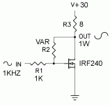
This was a real (not simulated) circuit. It is simplified in that I have
omitted the parts necessary to bias it.
😎
Attachments
Nelson Pass said:
This was a real (not simulated) circuit. It is simplified in that I have
omitted the parts necessary to bias it.
😎
A nice picture. It is back to JC's question about local VS global NFB
😎
Nelson Pass said:
I have measured this phenomenon with open loop distortions of 1%,
ten times better than the 10% you reference for Baxandall, but I still
see pretty much the same results. The higher harmonics jump in
with the application of low amounts of feedback and don't begin to
decline until the feedback exceeds 15 dB. Meanwhile the 2nd harmonic
drops proportionately with feedback.
Here's a copy of the graph, and of course I am happy to furnish
further details of the circuit.
😎
Hi Nelson,
You are exactly right. I also showed this phenomenon in an earlier post quite awhile back.
The key point to keep in mind is that, as you pointed out, things begin to decline eventually with higher amounts of negative feedback than about 15 dB. I showed that this relevant amount of feedback includes degeneration and local feedback. This means that if you designed a fairly linear open loop amplifier, you probably had some degeneration at minimum in the open-loop stages, so you are already beyond the 15 dB number before you even close the global loop. At that point, the application of additional negative feedback by global means begins to reduce all distortion from the get-go.
Cheers,
Bob
Wavebourn said:
Patrick, I use about 30 dB of global feedback in my tube amps, so measurable errors are almost those that are added by an error amp itself, i.e. the 1'st pentode stage. I don't know who invented the "low negative feedback is good" myth for tube amps; probably those who did not know how to deal with cheap output transformers (my speculation, of course). It's better not to use it at all instead of using "a bit".
Macintosh actually devised a way to get very large amounts of negative feedback around the output stage, where most distortion originates. It was called the unity-coupled output stage. It provided local NFB around the output stage in addition to the usual global NFB.
Cheers,
Bob
Bob Cordell said:
Macintosh actually devised a way to get very large amounts of negative feedback around the output stage, where most distortion originates. It was called the unity-coupled output stage. It provided local NFB around the output stage in addition to the usual global NFB.
If I remember right, they used voltage feedback in series with input using additional "cathode" transformer windings?
In my Pyramid-VII I used parallel feedback by voltage (think of it as an inverting opamp connection), from anode of each output tube to anode of corresponding driver one. In order to do so I had to use powerful pentodes as drivers. When I played with it I was getting oscillations with about 5 seconds period (can you imagine such a behaviour from output transformers?) when local feedback was too deep.
Bob Cordell said:I showed that this relevant amount of feedback includes degeneration and local feedback.
I have looked for similar creation of high order harmonics in FETs as a
function of degeneration, and provided that the variations in Vds
have been kept constant, I have not seen it.
I recall asking Pavel about this issue specifically with regards to
degeneration of cascoded JFETs in his simulations, but I don't recall
a clear answer.
😎
Let me try to clarify a bit what I was talking about in an earlier post. A couple of the replies I got indicated that I did not do a very good job of explaining what I was trying to do.
The idea was to try to figure out, without a lot of math or simulations, what Baxandall's graphs of distortion components vs. feedback would look like when the open-loop amplifier was more linear than what Baxandall assumed (but still having only second-harmonic distortion). My argument was that the curves for the various harmonic components would simply shift down, and using the weakly nonlinear assumption, I tried to calculate what that downward shift should be for each harmonic. However, one thing that's not clear is whether the weakly nonlinear assumption is still valid when the distortion of the open-loop amplifier is near 10 percent as in Baxandall's analysis. So I tried to look into this further using SPICE.
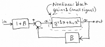
The block diagram attached below shows a nonlinear block, having only second-harmonic distortion, in a feedback loop. The nonlinear block has a small-signal gain of 1, and a parameter a2 to adjust the distortion. The feedback factor B is adjusted to vary the loop gain. Small-signal analysis shows that the small-signal gain of the overall system is exactly 1, independent of what B is. This circuit can be easily implemented in SPICE. The (1+B) block at the input is just a VCVS (E-source) of value (1+B). The feedback block is similar. The subtractor is just an E-source with a gain of 1, with the positive input hooked up to the output of the (1+B) block, and the negative input hooked up the the (B) feedback block. The nonlinear block is just a behavioral B-source with a small-signal gain of 1, and an adjustable parameter a2. So it's not necessary to use models of physical devices. This keeps things simple, allows precise control of the open-loop distortion, and ensures that the open-loop distortion is purely second-harmonic.
The feedback factor is stepped from 0 dB to 40 dB in 1 dB steps. This is done as follows:
.step param fbfact 0 40 1
.param B pow(10, fbfact/20)-1
Then 41 distortion simulations are done, and the LTspice error log containing the distortion components is pasted into Excel. Excel picks up the cell references and creates a graph from them. The input voltage is set to 1 Volt peak. With no feedback, this is also exactly the fundamental component of the output voltage. With this voltage amplitude, the a2 values are as follows:
a2 = 0.2 for 10 percent open-loop distortion
a2 = 0.02 for 1 percent open-loop distortion
a2 = 0.002 for 0.1 percent open-loop distortion
Three sets of simulations are run, producing 3 Baxandall-style graphs. I'll post these, and the simulation and Excel files in posts that follow.
The idea was to try to figure out, without a lot of math or simulations, what Baxandall's graphs of distortion components vs. feedback would look like when the open-loop amplifier was more linear than what Baxandall assumed (but still having only second-harmonic distortion). My argument was that the curves for the various harmonic components would simply shift down, and using the weakly nonlinear assumption, I tried to calculate what that downward shift should be for each harmonic. However, one thing that's not clear is whether the weakly nonlinear assumption is still valid when the distortion of the open-loop amplifier is near 10 percent as in Baxandall's analysis. So I tried to look into this further using SPICE.
The block diagram attached below shows a nonlinear block, having only second-harmonic distortion, in a feedback loop. The nonlinear block has a small-signal gain of 1, and a parameter a2 to adjust the distortion. The feedback factor B is adjusted to vary the loop gain. Small-signal analysis shows that the small-signal gain of the overall system is exactly 1, independent of what B is. This circuit can be easily implemented in SPICE. The (1+B) block at the input is just a VCVS (E-source) of value (1+B). The feedback block is similar. The subtractor is just an E-source with a gain of 1, with the positive input hooked up to the output of the (1+B) block, and the negative input hooked up the the (B) feedback block. The nonlinear block is just a behavioral B-source with a small-signal gain of 1, and an adjustable parameter a2. So it's not necessary to use models of physical devices. This keeps things simple, allows precise control of the open-loop distortion, and ensures that the open-loop distortion is purely second-harmonic.
The feedback factor is stepped from 0 dB to 40 dB in 1 dB steps. This is done as follows:
.step param fbfact 0 40 1
.param B pow(10, fbfact/20)-1
Then 41 distortion simulations are done, and the LTspice error log containing the distortion components is pasted into Excel. Excel picks up the cell references and creates a graph from them. The input voltage is set to 1 Volt peak. With no feedback, this is also exactly the fundamental component of the output voltage. With this voltage amplitude, the a2 values are as follows:
a2 = 0.2 for 10 percent open-loop distortion
a2 = 0.02 for 1 percent open-loop distortion
a2 = 0.002 for 0.1 percent open-loop distortion
Three sets of simulations are run, producing 3 Baxandall-style graphs. I'll post these, and the simulation and Excel files in posts that follow.
Attachments
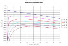
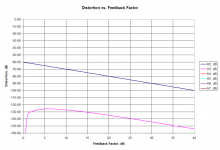
Here's the Baxandall plot for the case of 10 percent open-loop distortion. This is somewhat more pessimistic than Baxandall's original plot, since his open-loop distortion is slightly less than 10 percent (about -21 or -22 or so).
I have cut off all plots at -160 dB, as the simulated distortion gets very wobbly below that.
I have cut off all plots at -160 dB, as the simulated distortion gets very wobbly below that.
Attachments
Is there a reason why you don't set it for constant output amplitude
instead of constant input?
😎
instead of constant input?
😎
Nelson Pass said:Is there a reason why you don't set it for constant output amplitude
instead of constant input?
😎
It is (or very, very nearly so). The small-signal gain is constant, independent of B.
Edit: The feedback block has small-signal gain 1/(1+B), while the (1+B) block at the input forces the overall small-signal gain to 1.
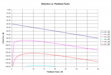
Thank you Andy, so your next set will be for the system with 1% open-loop distortion. Am I right?
Finally, I've attached a zip file below. This contains both the LTspice simulation and the Excel spreadsheet for graph creation. The spreadsheet is for the 10 percent open-loop distortion case.
The worksheet tab labeled "raw" contains the data pasted in from the LTspice error log. The cell references for the pasted data are joined together in the "for_graph" worksheet tab. Then they are converted to dB in another set of columns. This means you can reuse the spreadsheet. You might, for example, choose some other a2 value. As long as you select the data in the SPICE error log starting with ".step fbfact=0" and paste in the data for all 41 steps starting in the top left cell (A1), the spreadsheet will automatically pick up the new data and plot it. Other possibilities might be to add higher-order harmonics to the B-source that models the open-loop amplifier.
The worksheet tab labeled "raw" contains the data pasted in from the LTspice error log. The cell references for the pasted data are joined together in the "for_graph" worksheet tab. Then they are converted to dB in another set of columns. This means you can reuse the spreadsheet. You might, for example, choose some other a2 value. As long as you select the data in the SPICE error log starting with ".step fbfact=0" and paste in the data for all 41 steps starting in the top left cell (A1), the spreadsheet will automatically pick up the new data and plot it. Other possibilities might be to add higher-order harmonics to the B-source that models the open-loop amplifier.
Attachments
- Home
- Amplifiers
- Solid State
- Bob Cordell Interview: Negative Feedback