Re: NFB clamp
Well, there's another "duh!". The error is about 1/28 of what I thought it would be originally (1 percent of 80/G, not 1 percent of 80). I didn't think it through. This is much better than I originally thought 🙂.
Edmond Stuart said:If you use the same ratio for the feedback and clipping dividers, the only thing that matters is the input voltage, not that huge output voltage.
Well, there's another "duh!". The error is about 1/28 of what I thought it would be originally (1 percent of 80/G, not 1 percent of 80). I didn't think it through. This is much better than I originally thought 🙂.
Re: Re: Re: Nested clamp
Hi Edmond,
But of course! I had no problem with loop stability. When the Baker clamp activates, it is basically closing the same global FB loop, but BEFORE the output stage. The Baker clamp just diverts the VAS output signal current to form an alternate feedback path.
An interesting point is the following. How high an input signal do we wish the IPS-VAS to be able to handle in the presence of Baker clamped clipping of the overall amplifier. Obviously, at some point, a large enough signal will eventually clip the input stage. So how much above-clipping headroom do we want or need? And what happens when we run out of it?
Interestingly, although it is nice to be able to have the IPS-VAS still not clipping with a 6 dB overload from overall amplifier clipping, it turns out that such an amount of margin is often not necessary to prevent any evidence of sticking in the clipped amplifier output waveform. This is because the IPS-VAS signal margin above global clipping often gives the IPS-VAS time to recover before the Baker clamps release when coming out of clipping.
Cheers,
Bob
Edmond Stuart said:
Thanks Bob.
Using your words, great minds think alike. However, there's one caveat: loop stability!
Cheers,
Edmond.
Hi Edmond,
But of course! I had no problem with loop stability. When the Baker clamp activates, it is basically closing the same global FB loop, but BEFORE the output stage. The Baker clamp just diverts the VAS output signal current to form an alternate feedback path.
An interesting point is the following. How high an input signal do we wish the IPS-VAS to be able to handle in the presence of Baker clamped clipping of the overall amplifier. Obviously, at some point, a large enough signal will eventually clip the input stage. So how much above-clipping headroom do we want or need? And what happens when we run out of it?
Interestingly, although it is nice to be able to have the IPS-VAS still not clipping with a 6 dB overload from overall amplifier clipping, it turns out that such an amount of margin is often not necessary to prevent any evidence of sticking in the clipped amplifier output waveform. This is because the IPS-VAS signal margin above global clipping often gives the IPS-VAS time to recover before the Baker clamps release when coming out of clipping.
Cheers,
Bob
Re: Re: Re: Re: Nested clamp
Just connect the clamp diodes to the emitters of the pre-driver, driver or VAS buffer transistors instead of the VAS collector. Then the clamp will be able to track a much larger input signal. This works for unipolar VAS's too.
Bob Cordell said:
An interesting point is the following. How high an input signal do we wish the IPS-VAS to be able to handle in the presence of Baker clamped clipping of the overall amplifier. Obviously, at some point, a large enough signal will eventually clip the input stage. So how much above-clipping headroom do we want or need? And what happens when we run out of it?
Just connect the clamp diodes to the emitters of the pre-driver, driver or VAS buffer transistors instead of the VAS collector. Then the clamp will be able to track a much larger input signal. This works for unipolar VAS's too.
Here is one more way to skin the cat, I used in a hybrid power amp:
http://wavebourn.com/forum/viewtopic.php?p=22580#p22580
Compression when occurs sounds less nasty than clipping, but diode clipping don't need a time to react. It is a combination of diode clipping and compression.
So, when overdriven diodes flatten the peaks, current from them creates voltage drop on resistor from them to ground which is amplified by opamp opens the LED in Vactrol opto-pair increasing input attenuation. Current through LED is proportional to voltage of peaks clipped by diodes.
It still clipping, but almost inaudible (compared to clipping of a power amp, especially with deep feedback used, or a simple diode clipper).
Disadvantage: temperature dependence, so it would be nice to keep clipping diodes in a stable temperature environment.
Wavebourn said:Here is one more way to skin the cat, I used in a hybrid power amp:
http://wavebourn.com/forum/viewtopic.php?p=22580#p22580
Compression when occurs sounds less nasty than clipping, but diode clipping don't need a time to react. It is a combination of diode clipping and compression.
So, when overdriven diodes flatten the peaks, current from them creates voltage drop on resistor from them to ground which is amplified by opamp opens the LED in Vactrol opto-pair increasing input attenuation. Current through LED is proportional to voltage of peaks clipped by diodes.
It still clipping, but almost inaudible (compared to clipping of a power amp, especially with deep feedback used, or a simple diode clipper).
Disadvantage: temperature dependence, so it would be nice to keep clipping diodes in a stable temperature environment.
Anatolyi,
If I read that circuit correctly, the eastern side of R2 is the unbalanced signal to the rest of the amp? There's a lot of non-linear stuff at that point, doesn't that ruin the distortion performance?
Jan Didden
NFB clamp
Hi Bob,
I agree with that, at least, if the clamp works exactly like that. But the devil is in the detail. In my clamp circuit, the feedback current is derived from the drivers instead of the VAS output itself. Simulations reveal that the ULGF of the clamp loop was rather high (tens of MHZ) and the phase margin only moderate. Therefore, I added lead-lag compensation, just to be on the safe side.
Don't worry, as described above, the FB signal is derived from the drivers, so there is plenty of current available to prevent clipping of the IPS.
I also agree with that, though there might be an exception: when NDFL is applied as well. Generally, the NDFL stage contains quite a large capacitor and this one needs more time to recover from overcharging.
BTW, the PGP amp utilizes also an FB clamp, though it has been implemented in a different (and more clumsy) way. Here, the current through the Bake clamp is simply copied and this copy is fed back to the inverting input of the IPS. See (again): http://home.tiscali.nl/data.odyssey/PGP.html , fig.5 and 6.
Cheers,
Edmond.
Bob Cordell said:Hi Edmond,
But of course! I had no problem with loop stability. When the Baker clamp activates, it is basically closing the same global FB loop, but BEFORE the output stage. The Baker clamp just diverts the VAS output signal current to form an alternate feedback path.
Hi Bob,
I agree with that, at least, if the clamp works exactly like that. But the devil is in the detail. In my clamp circuit, the feedback current is derived from the drivers instead of the VAS output itself. Simulations reveal that the ULGF of the clamp loop was rather high (tens of MHZ) and the phase margin only moderate. Therefore, I added lead-lag compensation, just to be on the safe side.
An interesting point is the following. How high an input signal do we wish the IPS-VAS to be able to handle in the presence of Baker clamped clipping of the overall amplifier. Obviously, at some point, a large enough signal will eventually clip the input stage. So how much above-clipping headroom do we want or need? And what happens when we run out of it?
Don't worry, as described above, the FB signal is derived from the drivers, so there is plenty of current available to prevent clipping of the IPS.
Interestingly, although it is nice to be able to have the IPS-VAS still not clipping with a 6 dB overload from overall amplifier clipping, it turns out that such an amount of margin is often not necessary to prevent any evidence of sticking in the clipped amplifier output waveform. This is because the IPS-VAS signal margin above global clipping often gives the IPS-VAS time to recover before the Baker clamps release when coming out of clipping.
Cheers,
Bob
I also agree with that, though there might be an exception: when NDFL is applied as well. Generally, the NDFL stage contains quite a large capacitor and this one needs more time to recover from overcharging.
BTW, the PGP amp utilizes also an FB clamp, though it has been implemented in a different (and more clumsy) way. Here, the current through the Bake clamp is simply copied and this copy is fed back to the inverting input of the IPS. See (again): http://home.tiscali.nl/data.odyssey/PGP.html , fig.5 and 6.
Cheers,
Edmond.
Re: Re: Re: Re: Re: Nested clamp
Thank you so much for pointing out again what I've already said here: http://www.diyaudio.com/forums/showthread.php?postid=1825871#post1825871
G.Kleinschmidt said:Just connect the clamp diodes to the emitters of the pre-driver, driver or VAS buffer transistors instead of the VAS collector. Then the clamp will be able to track a much larger input signal. This works for unipolar VAS's too.
Thank you so much for pointing out again what I've already said here: http://www.diyaudio.com/forums/showthread.php?postid=1825871#post1825871
janneman said:
Anatolyi,
If I read that circuit correctly, the eastern side of R2 is the unbalanced signal to the rest of the amp? There's a lot of non-linear stuff at that point, doesn't that ruin the distortion performance?
No!
What ruins distortion performance, is the amp with deep feedback when starts clipping.
This thingy sits quiet until peaks are enough to create on R3 voltage drop enough to when amplified to fire a LED in an opto-isolator that forming R2/R6 divider increases attenuation.
Yes, smooth clipping presents, and the thingy keeps the signal smoothly clipped if it's level is too high; otherwise it would cause nasty clipping of an output amplifier.
But if an input level is properly set this thingy does nothing: peaks are lower than breakdown voltages of 2 diodes in series.
Re: NFB clamp
Hi Edmond,
I think we just have a philosophical difference and difference of approach here. I believe that diverting the current from the VAS for closing the loop with Baker clamps is far preferable to bringing back signal from the pre-driver. Bringing it back from the pre-driver results in significantly increased closed loop bandwidth when clippling occurs, necessitating additional compensation in the clamp loop. My approach requires no additional compensation whatsoever.
Cheers,
Bob
Edmond Stuart said:
Hi Bob,
I agree with that, at least, if the clamp works exactly like that. But the devil is in the detail. In my clamp circuit, the feedback current is derived from the drivers instead of the VAS output itself. Simulations reveal that the ULGF of the clamp loop was rather high (tens of MHZ) and the phase margin only moderate. Therefore, I added lead-lag compensation, just to be on the safe side.
Don't worry, as described above, the FB signal is derived from the drivers, so there is plenty of current available to prevent clipping of the IPS.
I also agree with that, though there might be an exception: when NDFL is applied as well. Generally, the NDFL stage contains quite a large capacitor and this one needs more time to recover from overcharging.
BTW, the PGP amp utilizes also an FB clamp, though it has been implemented in a different (and more clumsy) way. Here, the current through the Bake clamp is simply copied and this copy is fed back to the inverting input of the IPS. See (again): http://home.tiscali.nl/data.odyssey/PGP.html , fig.5 and 6.
Cheers,
Edmond.
Hi Edmond,
I think we just have a philosophical difference and difference of approach here. I believe that diverting the current from the VAS for closing the loop with Baker clamps is far preferable to bringing back signal from the pre-driver. Bringing it back from the pre-driver results in significantly increased closed loop bandwidth when clippling occurs, necessitating additional compensation in the clamp loop. My approach requires no additional compensation whatsoever.
Cheers,
Bob
Wavebourn said:
No!
What ruins distortion performance, is the amp with deep feedback when starts clipping.
This thingy sits quiet until peaks are enough to create on R3 voltage drop enough to when amplified to fire a LED in an opto-isolator that forming R2/R6 divider increases attenuation.
Yes, smooth clipping presents, and the thingy keeps the signal smoothly clipped if it's level is too high; otherwise it would cause nasty clipping of an output amplifier.
But if an input level is properly set this thingy does nothing: peaks are lower than breakdown voltages of 2 diodes in series.
My point is that you have a couple of diodes and 10k as load hanging at the signal with source impedance of 1k. I know that we usually look at diodes as something that doesn't conduct below 0.6V or so, but that's a very gross simplification.
Your string of 2 diodes is supposed to come into action at say 1.2V signal peak, but a quick sim shows that the diodes already conduct 1uA at 2*360mV = 720mV.
The 1uA current across that 1k source clips 1mV from the 700mV. Assuming for kicks it actually was 1mV from 1000mV that's -60dB.
I know you can't just transfer that to -60dB distortion, and I also disregarded that 10k in the load, but it does show that that kind of network ususally has a far greater impact then it looks at first glance.
Jan Didden
janneman said:
My point is that you have a couple of diodes and 10k as load hanging at the signal with source impedance of 1k. I know that we usually look at diodes as something that doesn't conduct below 0.6V or so, but that's a very gross simplification.
Your string of 2 diodes is supposed to come into action at say 1.2V signal peak, but a quick sim shows that the diodes already conduct 1uA at 2*360mV = 720mV.
The 1uA current across that 1k source clips 1mV from the 700mV. Assuming for kicks it actually was 1mV from 1000mV that's -60dB.
I know you can't just transfer that to -60dB distortion, and I also disregarded that 10k in the load, but it does show that that kind of network ususally has a far greater impact then it looks at first glance.
Yesterday I regret I did not have such a network available, or even worse: a simple rough diode clipper. After a concert DJ used my equipment for dances. He tried to get "the sound" he needed, but the system refused to give it to him: my power amps have anti-clipping optical compressors. When I realized what he wants, I pulled down master faders on the mixing console, at the same time increasing sensitivity of the stereo channel. The channel started clipping, that made the DJ feel home.
😎
Re: Re: NFB clamp
Hi John,
Again, the devil is in the detail. I did some further sims (with 6db overdrive) on the circuit shown here: http://www.diyaudio.com/forums/showthread.php?postid=1801149#post1801149
and the results are more or less counterintuitive:
FB from the VAS output without compensation:
DC loop gain = 20dB
ULGF = 28MHz
PM = 52 degrees. Hmm... it's stable, but could be better.
FB from the VAS output with compensation:
DC loop gain = 20dB
ULGF = 4.3MHz
PM = 115 degrees. That's really nice.
FB from the pre-driver without compensation:
DC loop gain = 45dB. Much higher as expected.
ULGF = 33MHz. Huh?... Only 5 MHz higher?
PM = 35 degrees. This margin is too small.
FB from the pre-driver with compensation:
DC loop gain = 45dB
ULGF = 10MHz
PM = 60 degrees. That's just okay.
As you see, at the DC level, the loop gain, as predicted, is much larger when the FB is taken from the (pre) driver. At high frequencies however, the picture is completely different. ULGF 33 vs 28 MHz, for example. So the loop gains at these frequencies are also lying much closer to each other. The reason is that, opposed to LF, at HF the output impedance of the VAS approaches the Zo of the next stage (due to the Miller effect).
BTW, this effect is also illustrated (or confirmed if you like) by the observation that at HF, the voltage component of the FB signal takes over the current component dominating at LF.
Apart from many other details that will certainly have an effect on loop stability too, your approach and no additional compensation stuff will indeed suffice. But, if the FB signal is taken from the (pre)driver for whatever reason, additional compensation is definitely needed.
Cheers,
Edmond.
Bob Cordell said:Hi Edmond,
I think we just have a philosophical difference and difference of approach here. I believe that diverting the current from the VAS for closing the loop with Baker clamps is far preferable to bringing back signal from the pre-driver. Bringing it back from the pre-driver results in significantly increased closed loop bandwidth when clippling occurs, necessitating additional compensation in the clamp loop. My approach requires no additional compensation whatsoever.
Cheers,
Bob
Hi John,
Again, the devil is in the detail. I did some further sims (with 6db overdrive) on the circuit shown here: http://www.diyaudio.com/forums/showthread.php?postid=1801149#post1801149
and the results are more or less counterintuitive:
FB from the VAS output without compensation:
DC loop gain = 20dB
ULGF = 28MHz
PM = 52 degrees. Hmm... it's stable, but could be better.
FB from the VAS output with compensation:
DC loop gain = 20dB
ULGF = 4.3MHz
PM = 115 degrees. That's really nice.
FB from the pre-driver without compensation:
DC loop gain = 45dB. Much higher as expected.
ULGF = 33MHz. Huh?... Only 5 MHz higher?
PM = 35 degrees. This margin is too small.
FB from the pre-driver with compensation:
DC loop gain = 45dB
ULGF = 10MHz
PM = 60 degrees. That's just okay.
As you see, at the DC level, the loop gain, as predicted, is much larger when the FB is taken from the (pre) driver. At high frequencies however, the picture is completely different. ULGF 33 vs 28 MHz, for example. So the loop gains at these frequencies are also lying much closer to each other. The reason is that, opposed to LF, at HF the output impedance of the VAS approaches the Zo of the next stage (due to the Miller effect).
BTW, this effect is also illustrated (or confirmed if you like) by the observation that at HF, the voltage component of the FB signal takes over the current component dominating at LF.
Apart from many other details that will certainly have an effect on loop stability too, your approach and no additional compensation stuff will indeed suffice. But, if the FB signal is taken from the (pre)driver for whatever reason, additional compensation is definitely needed.
Cheers,
Edmond.
 Oops! I mean 'Hi Bob', sorry.
andy_c said:
That's exactly right - the PSRR mod. Sticking was godawful with a normal clamp and did indeed require the feedback clamp to avoid that mess.
I'm playing with this PSRR mod now and have found that the clipping performance can be made rather good with just a diode clamp on the LTP and a voltage clamp on the VAS as shown in that other thread.
Just out of curiosity, why did you chose to return the "Miller" cap to the LTP cascode instead of the inverting input? Symmetrical (but slower) slewing with the unipolar VAS? Or did you find that it performed better in some other way?
Also, do you intend to bandwidth limit the input signal to prevent the TPC overshoot? D.Self in one of his later books made some interesting measurements on the non-linearity incurred by the LTP transistor base currents with resistances >50 ohms in series with the input, that I think is relevant here.
For instance, with a 51 ohm input resistor you'de need a 10nF cap to limit the bandwidth to 300kHz. That might be too heavy a load for some sources.
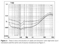
The attachment below is from “Self On Audio”, page 313.
Cheers,
Glen
Attachments
G.Kleinschmidt said:I'm playing with this PSRR mod now and have found that the clipping performance can be made rather good with just a diode clamp on the LTP and a voltage clamp on the VAS as shown in that other thread.
Hmm, I should revisit that. I've been having lots of trouble with convergence in my simulations of this amp. At the moment, I'm using transient and .SAVEBIAS / .LOADBIAS to make it all work. But if the circuit is not stable, the transient sim for finding the operating point can break into oscillation, making it nearly impossible to get to the point of .SAVEBIAS. This can be a real PITA when you're trying to figure out what it takes to make it stable to begin with 🙂. Last time I tried your clamping arrangement, I had this problem. This isn't a ding on your circuit in any way, but just a SPICE quirk.
Just out of curiosity, why did you chose to return the "Miller" cap to the LTP cascode instead of the inverting input? Symmetrical (but slower) slewing with the unipolar VAS? Or did you find that it performed better in some other way?
Oh, that was just the standard PSRR mod as originally described in the paper by Sackinger et. al. I assume you're referring to Bob's approach of including the input stage in the integrator loop? One thing I found with that is that the feedback resistors end up being pretty small, so the power dissipation in them gets pretty large for an output voltage swing of 80V peak.
Also, do you intend to bandwidth limit the input signal to prevent the TPC overshoot? D.Self in one of his later books made some interesting measurements on the non-linearity incurred by the LTP transistor base currents with resistances >50 ohms in series with the input, that I think is relevant here.
Yes. I'm currently planning for 1.37k and 470pF. I'm using TMC rather than TPC, so the overshoot isn't a problem. The LPF is to meet the "clips before it slew rate limits with a square wave" criterion. The bootstrapped cascoding seems to take care of the input stage distortion in simulation anyway. There's two levels of cascoding in the input stage - the bootstrap thing a la the LM108, and a fixed-base-voltage cascode for the PSRR mod.
For instance, with a 51 ohm input resistor you'de need a 10nF cap to limit the bandwidth to 300kHz. That might be too heavy a load for some sources.
I ended up doing distortion sims using device models for the input stage, with VAS and output stages implemented with ideal controlled sources (but modeling the frequency compensation so the input stage was loaded correctly). This was to get an idea of the contribution of input stage distortion to the overall distortion. The bootstrapped cascoding of the input stage seems to make the input stage distortion quite negligible compared to the rest of the amp, so I'm betting on it being okay. This sim included the effects of the input LPF. Diff amp trannies are BC560C, so nice high beta and cheaper than dirt. By tweaking model parameters in SPICE, I found the input stage distortion without bootstrapped cascoding was split about 65/35 between nonlinear Ccb and Early effect (full power at 20 kHz).
The attachment below is from “Self On Audio”, page 313.
That's a good one that I hadn't looked at before. I have a cascoded CCS for the LTP, and the supply for all but the output stage FETs will be regulated, so assuming proper grounding, I think I'll be in good shape.
My mistake. From memory of some previous discussion I though you were using TPC. I should have looked closer at that pic you linked to.
It looks like TPC the way I drew it 🙂. BTW, thanks for posting that D. Self reference. I have that book but haven't read it nearly as closely as his power amp book. I'm going to reduce the resistor in my input LPF I think.
Hi Glen
---The attachment below is from “Self On Audio”, page 313.---
Using CFP's input instead of single biploars, this problem would disappear, would'nt it ?
---The attachment below is from “Self On Audio”, page 313.---
Using CFP's input instead of single biploars, this problem would disappear, would'nt it ?
- Home
- Amplifiers
- Solid State
- Bob Cordell Interview: Negative Feedback