Re: Re: NDFL
Hi Glen,
Here's the original Alexander amp:
http://www.analog.com/static/import...tes/58052492001115525484056221917334AN211.pdf
(contact me for a less cluttered schematic)
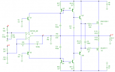
And below a very basic NDFL variant stripped down from all bells and whistles for clarity, hence a mediocre performance.
Cheers,
Edmond.
PS: I can't remember how I've calculated the various RC values, as it is too long ago, but the step response looks okay.
G.Kleinschmidt said:.......
I've never really looked at the Alexander amp, but when you find your files post them up, they should be interesting.
Cheers,
Glen
Hi Glen,
Here's the original Alexander amp:
http://www.analog.com/static/import...tes/58052492001115525484056221917334AN211.pdf
(contact me for a less cluttered schematic)
And below a very basic NDFL variant stripped down from all bells and whistles for clarity, hence a mediocre performance.
Cheers,
Edmond.
PS: I can't remember how I've calculated the various RC values, as it is too long ago, but the step response looks okay.
Attachments
Re: Re: Re: NDFL
Maybe I'm wrong. AFAIK, Cherry has never published about TMC.
traderbam said:............
TMC - "transitional miller compensation" (c. Ed) is more complicated and involves taking the VAS/miller stage FB from the output at low f and then from some earlier point in the circuit at high f. Originally published by Cherry.
..........
Maybe I'm wrong. AFAIK, Cherry has never published about TMC.
I'm probably wrong. I haven't read his papers. I know he proposed the bit about including the OS in the miller loop; perhaps he didn't go as far as the transition at high f. Which is a surprise because I reckon its touch and go in practice, otherwise.
> I know he proposed the bit about including the OS in the miller loop.
That's right. But instead of TMC he proposed other means to avoid oscillations. See: EW, July 1997, p. 580.
Regards,
Edmond.
That's right. But instead of TMC he proposed other means to avoid oscillations. See: EW, July 1997, p. 580.
Regards,
Edmond.
Re: Re: Re: NDFL
That's a pretty good summary, and mirrors my understanding as well. With one amendment: to me, NDFL is nothing more than a particular case of NPC (N pole compensation) or otherwise put, TPC is a particular case of NDFL. Or even otherwise put, NDFL is a TPC generalisation.
Now, I am ready to admit I'm an cranky old fart that usually can't tell my *** from a hole in the wall. I would love to have an answer to the following:
Consider a fixed base amp, of known characteristics, ideally something that can be simply implemented in the real life, but for the sake of this discussion abstract models (like e.g. an ideal opamp with a single pole response and a given nonlinearity) are acceptable, and choose a set of target performances (TBD, list is open, this is where the discussion should start).
1. What are the advantages and disadvantages of TPC.
2. What are the advantages and disadvantages of TMC.
3. What can I do in TPC that I can't do in TMC.
4. What can I do in TMC that I can't do in TPC.
5. Are there any base amp requirements to make TPC more effective.
6. Are there any base amp requirements to make TMC more effective.
7. When should TPC be used to improve the target performances.
8. When should TMC be used to improve the target performances.
Numbers please, tables, diagrams, perhaps equations, only reproductible simulations with clear models. An let's accept that there isn't a one size fits all solution. These are the answers I got so far, let's try and go beyond this:
1. None, everything.
2. Everything, none.
3. Nothing.
4. Everything.
5. Yes.
6. No.
7. Never.
8. Always.
traderbam said:
I picked up the wrong end of the wrong stick by sticking my nose in! I admit I haven't read the thread in much detail and don't know why you were discussing TPC.
Anyhow, my understanding is that:
TPC - 2 pole compensation involves rolling off the fwd transfer function at 12dB/oct then pulling it back with a zero to 6dB/oct before the ULG f.
TMC - "transitional miller compensation" (c. Ed) is more complicated and involves taking the VAS/miller stage FB from the output at low f and then from some earlier point in the circuit at high f. Originally published by Cherry.
NDFL - is about wrapping NFB circuits within other NFB circuits, each outer circuit having a lower UGB than the inner one. Originally published by Cherry.
If that's right, then TPC with phase lead compensation is quite different from NDFL. NDFL is more bandwidth efficient in terms of poles/stages per increase in excess gain. TPC without compensation will always overshoot. In Ed's TPC example that Andy and I were analysing, the compensation to eliminate overshoot that I simulated is a network in the FB path consisting of 1.3k||1nF in series and 1k in shunt.
You seemed to be arguing against TMC and in favour of TPC. I haven't read back far enough to know why you were doing that - but arguing with Ed is good sport so who cares 😀 . Ed complained about the overshoot. Your rebuttal was to put an LPF on the amp input. Ed said this was pants because it ignored the problem. I then said a filter is needed in the FB path. Ed said true but it requires an unacceptable extension of the ULG f. I then simulated a solution that has the same ULG f, no overshoot and costs some 4dB of excess gain.

That's a pretty good summary, and mirrors my understanding as well. With one amendment: to me, NDFL is nothing more than a particular case of NPC (N pole compensation) or otherwise put, TPC is a particular case of NDFL. Or even otherwise put, NDFL is a TPC generalisation.
Now, I am ready to admit I'm an cranky old fart that usually can't tell my *** from a hole in the wall. I would love to have an answer to the following:
Consider a fixed base amp, of known characteristics, ideally something that can be simply implemented in the real life, but for the sake of this discussion abstract models (like e.g. an ideal opamp with a single pole response and a given nonlinearity) are acceptable, and choose a set of target performances (TBD, list is open, this is where the discussion should start).
1. What are the advantages and disadvantages of TPC.
2. What are the advantages and disadvantages of TMC.
3. What can I do in TPC that I can't do in TMC.
4. What can I do in TMC that I can't do in TPC.
5. Are there any base amp requirements to make TPC more effective.
6. Are there any base amp requirements to make TMC more effective.
7. When should TPC be used to improve the target performances.
8. When should TMC be used to improve the target performances.
Numbers please, tables, diagrams, perhaps equations, only reproductible simulations with clear models. An let's accept that there isn't a one size fits all solution. These are the answers I got so far, let's try and go beyond this:
1. None, everything.
2. Everything, none.
3. Nothing.
4. Everything.
5. Yes.
6. No.
7. Never.
8. Always.
Re: Re: Re: NDFL
Well that is exactly what NDF involves (using phase lead).
Not sure what gave you that idea. Edmond raised a BS flag and claimed that the input filter would not mask the TPC overshoot. I just attempted to show that that isn't the case. This has nothing to do with TMC per se. Nada, nill.
As for TPC Vs TMC it is application specific and the are clear cut examples (discussed to death already) where one has a definite advantage over the other.
Cheers,
Glen
traderbam said:TPC - 2 pole compensation involves rolling off the fwd transfer function at 12dB/oct then pulling it back with a zero to 6dB/oct before the ULG f.
Well that is exactly what NDF involves (using phase lead).
traderbam said:You seemed to be arguing against TMC and in favour of TPC. I haven't read back far enough to know why you were doing that - but arguing with Ed is good sport so who cares 😀 . Ed complained about the overshoot. Your rebuttal was to put an LPF on the amp input. Ed said this was pants because it ignored the problem. [/B]
Not sure what gave you that idea. Edmond raised a BS flag and claimed that the input filter would not mask the TPC overshoot. I just attempted to show that that isn't the case. This has nothing to do with TMC per se. Nada, nill.
As for TPC Vs TMC it is application specific and the are clear cut examples (discussed to death already) where one has a definite advantage over the other.
Cheers,
Glen
Re: Re: Re: Re: NDFL
Could you point me to these discussions? I can't recall any clear cut, only noise.
G.Kleinschmidt said:
As for TPC Vs TMC it is application specific and the are clear cut examples (discussed to death already) where one has a definite advantage over the other.
Could you point me to these discussions? I can't recall any clear cut, only noise.
Re: Re: Re: Re: NDFL
The only person who is clearly not "beyond this" so far is you.
It has been pointed out numerous times that for TMC to be significantly effective (or comparable to TPC) that the output stage must be the dominant source of non-linearity.
syn08 said:6. Are there any base amp requirements to make TMC more
<snip>These are the answers I got so far, let's try and go beyond this
6. No
The only person who is clearly not "beyond this" so far is you.
It has been pointed out numerous times that for TMC to be significantly effective (or comparable to TPC) that the output stage must be the dominant source of non-linearity.
Re: Re: Re: Re: Re: NDFL
See my post above.
syn08 said:
Could you point me to these discussions? I can't recall any clear cut, only noise.
See my post above.
Re: Re: Re: NDFL
Thanks Edmond, I'll give it a look.
Cheers,
Glen
Edmond Stuart said:
Hi Glen,
Here's the original Alexander amp:
http://www.analog.com/static/import...tes/58052492001115525484056221917334AN211.pdf
(contact me for a less cluttered schematic)
And below a very basic NDFL variant stripped down from all bells and whistles for clarity, hence a mediocre performance.
Cheers,
Edmond.
PS: I can't remember how I've calculated the various RC values, as it is too long ago, but the step response looks okay.
Thanks Edmond, I'll give it a look.
Cheers,
Glen
Re: Re: Re: Re: NDFL
 imagination.
How so?G.Kleinschmidt said:Well that is exactly what NDF involves (using phase lead).
MyNot sure what gave you that idea.
imagination.Re: Re: Re: Re: NDFL

Glen, I said that a typical input filter would not mask the overshoot. Later on (post 2715) I admitted that a LP filter with lower Fc does mask the overshoot. Furthermore, I said it is a stopgap, as it only suppresses the symptoms of the poor phase response of TPC, instead of curing it (or words of similar import).
Cheers,
Edmond.
G.Kleinschmidt said:...........
Not sure what gave you that idea. Edmond raised a BS flag and claimed that the input filter would not mask the TPC overshoot. I just attempted to show that that isn't the case. This has nothing to do with TMC per se
...........
Cheers,
Glen
Glen, I said that a typical input filter would not mask the overshoot. Later on (post 2715) I admitted that a LP filter with lower Fc does mask the overshoot. Furthermore, I said it is a stopgap, as it only suppresses the symptoms of the poor phase response of TPC, instead of curing it (or words of similar import).
Cheers,
Edmond.
Re: Re: Re: Re: Re: NDFL
How not so? Look back at the NDFL amp sim I posted some pages back, based on Cherry's design.
Following the long tail pair input stage there are two intergrators in series (the rush current amplifier stage followed by a miller compensated VAS) giving a -40dB/decade open loop roll off. Phase lead feedback from the output back to the input of the Rush current amplifier / intergrator stage completes the NDF loop and returns the open loop roll-off to -20dB/decade at about 1/5 the ULGF.
Your definition of an input filter (3.38MHz - 100R/470p) is NOT "typical" !!!!!!!

EDIT:
It is midnight already, I'm going bedybyes.
traderbam said:How so?
How not so? Look back at the NDFL amp sim I posted some pages back, based on Cherry's design.
Following the long tail pair input stage there are two intergrators in series (the rush current amplifier stage followed by a miller compensated VAS) giving a -40dB/decade open loop roll off. Phase lead feedback from the output back to the input of the Rush current amplifier / intergrator stage completes the NDF loop and returns the open loop roll-off to -20dB/decade at about 1/5 the ULGF.
Edmond Stuart said:
Glen, I said that a typical input filter would not mask the overshoot. Later on (post 2715) I admitted that a LP filter with lower Fc does mask the overshoot. Furthermore, I said it is a stopgap, as it only suppresses the symptoms of the poor phase response of TPC, instead of curing it (or words of similar import).
Cheers,
Edmond.
Your definition of an input filter (3.38MHz - 100R/470p) is NOT "typical" !!!!!!!
EDIT:
It is midnight already, I'm going bedybyes.
Re: Re: Re: Re: NDFL
At your service.
But don't put your expectations too high, as it was only meant as an explorative experiment.
Cheers,
Edmond.
 Discussed to death already.
Shouldn't we just ignore that noisy H.O.W.
G.Kleinschmidt said:Thanks Edmond, I'll give it a look.
Cheers,
Glen
At your service.
But don't put your expectations too high, as it was only meant as an explorative experiment.
Cheers,
Edmond.
G.Kleinschmidt said:As for TPC Vs TMC it is application specific and the are clear cut examples (discussed to death already) where one has a definite advantage over the other.
Discussed to death already.Shouldn't we just ignore that noisy H.O.W.
Re: Re: Re: Re: NDFL
You may be right. I'd need to scrape some pencil lead to be sure. For sake of discussion I'll assume NDFL is different from NPC (n pole comp) at least in the respect that NPC can only use one FB loop.
My intuition is that the use of multiple FB loops invokes more powerful magic from the Gods than a single FB loop. I reckon the nesting allows the control systems to pack the poles up more tightly for the same step response.
Brian
syn08 said:That's a pretty good summary, and mirrors my understanding as well. With one amendment: to me, NDFL is nothing more than a particular case of NPC (N pole compensation) or otherwise put, TPC is a particular case of NDFL. Or even otherwise put, NDFL is a TPC generalisation.
You may be right. I'd need to scrape some pencil lead to be sure. For sake of discussion I'll assume NDFL is different from NPC (n pole comp) at least in the respect that NPC can only use one FB loop.
My intuition is that the use of multiple FB loops invokes more powerful magic from the Gods than a single FB loop. I reckon the nesting allows the control systems to pack the poles up more tightly for the same step response.
Brian
Re: Re: Re: Re: Re: NDFL
Hi Brian,
Bruce Candy of Halcro has a later patent than his error correction patent that looks a lot like some kind of N-pole compensation, or maybe is a relative of NDFL, I'm not sure. Sorry, I don't have that patent number handy right now. I don't know if he put that into his newer amplifiers (superceding his HEC implementations) or not.
Cheers,
Bob
traderbam said:
You may be right. I'd need to scrape some pencil lead to be sure. For sake of discussion I'll assume NDFL is different from NPC (n pole comp) at least in the respect that NPC can only use one FB loop.
My intuition is that the use of multiple FB loops invokes more powerful magic from the Gods than a single FB loop. I reckon the nesting allows the control systems to pack the poles up more tightly for the same step response.
Brian
Hi Brian,
Bruce Candy of Halcro has a later patent than his error correction patent that looks a lot like some kind of N-pole compensation, or maybe is a relative of NDFL, I'm not sure. Sorry, I don't have that patent number handy right now. I don't know if he put that into his newer amplifiers (superceding his HEC implementations) or not.
Cheers,
Bob
Bob,
The Halcro patent is US 6798285.
He is basically describing an NDFL involving 1st and 2nd order filters.
Attached is an LTSpice model to play with, using the component values and CL gain of 30 as per the patent. I've assumed a 10MHz bandwidth OS. The circuit applies 144dB of excess gain at 20kHz and it rings like a bell with these values.
In an earlier post I estimated that the critically damped excess gain of a simple four (1st order) stage NDFL is 102dB, assuming a 30dB CL gain.
Brian
Attachments
traderbam said:Bob,
The Halcro patent is US 6798285.
He is basically describing an NDFL involving 1st and 2nd order filters.
Attached is an LTSpice model to play with, using the component values and CL gain of 30 as per the patent. I've assumed a 10MHz bandwidth OS. The circuit applies 144dB of excess gain at 20kHz and it rings like a bell with these values.
In an earlier post I estimated that the critically damped excess gain of a simple four (1st order) stage NDFL is 102dB, assuming a 30dB CL gain.
Brian
Thanks, Brian. I'll give it a look.
Cheers,
Bob
Halcro
Hi Brian,
According my simulation it rings like hell at 800kHz with 50% overshoot. Did I something wrong?
Regards,
Edmond.
traderbam said:.......
and it rings like a bell with these values.
........
Hi Brian,
According my simulation it rings like hell at 800kHz with 50% overshoot. Did I something wrong?
Regards,
Edmond.
Here are a few old-ish articles that might bring some new/fresh ideas on how to implement a low distortion audio amp... I scanned these in diagonal, they all seem to be very interesting, I'll take a closer look as soon as I'll get some time... There are only so many hours a day, and a few have to go to %&^% sleep 🙁
http://diyaudio.org.ua/download/file.php?id=663&sid=7aba0256273a9e2f3e979549a484b8dd
http://diyaudio.org.ua/download/file.php?id=677&sid=7aba0256273a9e2f3e979549a484b8dd
http://diyaudio.org.ua/download/file.php?id=675&sid=7aba0256273a9e2f3e979549a484b8dd
http://diyaudio.org.ua/download/file.php?id=674&sid=7aba0256273a9e2f3e979549a484b8dd
http://diyaudio.org.ua/download/file.php?id=679&sid=7aba0256273a9e2f3e979549a484b8dd
http://diyaudio.org.ua/download/file.php?id=678&sid=7aba0256273a9e2f3e979549a484b8dd
http://diyaudio.org.ua/download/file.php?id=668&sid=7aba0256273a9e2f3e979549a484b8dd
http://diyaudio.org.ua/download/file.php?id=665&sid=7aba0256273a9e2f3e979549a484b8dd
As usual, download the articles ASAP, you'll never know for how long these links are up...
- Home
- Amplifiers
- Solid State
- Bob Cordell Interview: Negative Feedback