Edmond Stuart said:Well, that's rather obvious, isn't it?
Thanks, great answer. I thought the same, but the results are not as expected.
syn08 said:I'm not reading directly the simmie-boy posts, but seeing your quote and after rolling a few times under the table I can't stop sharing this:
A 1Kohm resistor in the input filter has a Johnson noise of 4nV/rtHz. That is, about 600nV in 20-20KHz. Multiply this by, say, a gain of 30 and you get a nice 18uV (eighteen microvolts) RMS noise voltage at the speaker. That is, a power of 8.1E-13W into 4ohmBoy, this is loud!
Agreed, moaning about 8.1E-13W noise is ridiculous.
>I'm not reading directly the simmie-boy posts
So you are commenting on something you haven't even read?

If you have done it, you know that nobody mentioned 1kOhm.
But let's have some more fun. I know someone who dreamed about a power amp with all disturbances, THD, IMD, hum, noise etc. below -120dB. During a year or so he invested a great deal of his spare time in this project. Also, he invested thousand of $$ in measurement equipment. And of course, only the lowest noise trannies were good enough. BTW, this only makes sens if you keep all impedances at the input as low as possible. Last but least, he also was very concerned about the noise (if any) of LEDs at places where they can't do any harm.
Now I wander, could anybody hear the difference between that amp with such exceptional specs compared to amps with more common specs?
OK, so this is the Romper Room thread now 🙄
Regarding "transient perfect" amplifiers, do you remember my K12A TMC amp, fully differential with the I-mirrored LTP's?
Well with the type of compensation above applied that is exactly what it is.
It also has ship hot slewing performance because the VAS peak current limits at 6 times the standing current (thanks to those current mirrors on the LTP's).
I'm developing a quad of these (modified for +/-80V rails) for a monster fully balanced (bridged) stereo amplifier I'm putting together, christened the "Beast".
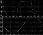
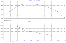
Here is what I get for the squarewave and clipping response with excessive (to be on the conservative side) compensation and load capacitance on the VAS collector
Regarding "transient perfect" amplifiers, do you remember my K12A TMC amp, fully differential with the I-mirrored LTP's?
Well with the type of compensation above applied that is exactly what it is.
It also has ship hot slewing performance because the VAS peak current limits at 6 times the standing current (thanks to those current mirrors on the LTP's).
I'm developing a quad of these (modified for +/-80V rails) for a monster fully balanced (bridged) stereo amplifier I'm putting together, christened the "Beast".
Here is what I get for the squarewave and clipping response with excessive (to be on the conservative side) compensation and load capacitance on the VAS collector
Attachments


G.Kleinschmidt said:........
Regarding "transient perfect" amplifiers, do you remember my K12A TMC amp, fully differential with the I-mirrored LTP's?
...................
Yes, I do. Regrettably, I also remember I did a lot of simulations for you. In the mean time, I've learned my lessons. Not interested in negative pay-off.
G.Kleinschmidt said:Now for something completely different.
Take that schematic of BC's amplifier attached. Suppose the Miller loop is to be compensated with an RC from the VAS collector to ground instead of as a shunt on the LTP.
Where does the loop gain probe go to investigate the Miller (not the global) loop phase margin? I'm getting results that don't make much sense at the moment.
Cheers,
Glen
As I said before, at the obvious place.
If the new R=100 Ohms and C=100pF the result is not really promising. PM = only a few degrees.
edit: probe between C4 and R13
Attachments
andy_c said:Well, I just played around with this a bit in MathCad. I assumed the loop gain AB = K(s + a) / s2. At high enough frequencies, this can be approximated as K/s, so K is approximately the unity loop gain freq in rad/sec. Then calculating AB / (1 + AB), you get:
K(s + a) / (s2 + Ks + Ka)
Picking the ULG freq to be 1 MHz, this gives K = 2 * pi * 1e6. The zero (a) is 2 * pi * 200e3, assuming we set this to 1/5 of the ULG freq. Then the roots of the denominator can easily be found. This gives two poles, at f1 and f2. The results are:
f1 = 276.4 kHz and
f2 = 723.6 kHz
You end up with a zero at 200 kHz, then a pole at 276.4 kHz, then another pole at 723.6 kHz. So you can see how the overshoot happens. Blowing up the frequency response should show a very small shelf near the zero.
Edit: I'm assuming resistive feedback (B = constant)
Andy, are you really bored or what? 😉
You can't be as bored as me or you would have also calculated the overshoot for a step input to be 11.6% after 690ns.
The only way to eliminate the overshoot is, of course, to cancel the zero with either of the poles, which is not possible.
Attachments
Edmond Stuart said:
As I said before, at the obvious place.
If the new R=100 Ohms and C=100pF the result is not really promising. PM = only a few degrees.
edit: probe between C4 and R13
LOL!
That is the same result I got, but I didn't think it was right as I needed such a huge capacitance on the VAS collector to get a decent Miller loop phase margin.
Bob Cordell suggested compensating the Miller loop this way to avoid the rail sticking caused by the RC on the LTP (I raised this issue in this thread a month or so ago). However it seems rather ineffectual for some reason. It is midnight now and my brain hurts, but I wonder if in trying to compensate the Miller loop this way one is fruitlessly fighting against a pole-splitting effect?
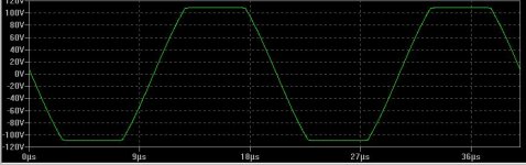
Anyway, I was wasting my time because it turns out that my 12W amp topology is pretty much immune to this sticking effect for some reason. With a pair of 150pF caps connected across the VAS biasing / LTP load resistors for a much more healthy Miller loop phase margin of ~85 degrees my slew rate is still around 1000V/us for the bridged amp and on clipping there is only about 40nS of rail sticking, not even visible on a 50kHz sinewave:
😎
Attachments
Perhaps now you understand why I prefer first doing a sim and then offer a suggestion. No-one wants to be fobbed off with something that doesn't work.
BTW, sleep well.
BTW, sleep well.
traderbam said:Andy, are you really bored or what? 😉
Well, I stopped taking part in one particular thread that was more of a fraud investigation than any sort of technical undertaking. That freed up some time. I'm sure you know the thread I'm talking about 🙂.
You can't be as bored as me or you would have also calculated the overshoot for a step input to be 11.6% after 690ns.
The only way to eliminate the overshoot is, of course, to cancel the zero with either of the poles, which is not possible.
As Glen mentioned, the input LPF can be used to take care of it as well. Putting the pole of the input LPF at the same frequency as the open-loop zero will always do the job, and in practice the LPF pole can be at a higher frequency than the open-loop zero. But yeah, some sort of LPF action is needed. I don't consider that a big deal though.
Oh yeah, the other interesting thing is the critical damping condition. That happens when the ULG frequency is at 4x the frequency of the zero. Then the poles are both at one-half of the ULG frequency.
Edmond Stuart said:BTW, sleep well.
Having sorted my compensation dilemma I did. BTW does that coil company export? I could use one of those for one of my amps 🙂
The ultimate coil
Sure. In addition, they sell a water cooled version as well, of course also inductance free, and especially tailored for 1MW audio amps 😉
G.Kleinschmidt said:..............
BTW does that coil company export? I could use one of those for one of my amps 🙂
Sure. In addition, they sell a water cooled version as well, of course also inductance free, and especially tailored for 1MW audio amps 😉
Re: Re: Re: Down with NDFL
Compared to Bob's kind of Miller compensation, which doesn't load the LTP at all, NDFL creates even one more source of distortion by loading the LTP with a R-C network connected to the output (i.e. in your schematic R10 and C3, http://www.diyaudio.com/forums/showthread.php?postid=1770933#post1770933 ).
It's just like software, removing one one bug creates two new bugs (at least at micro$hoft).
BTW, in the PGP amp I've circumvented this by leading the nested FB loop also to the inverting input.
G.Kleinschmidt said:..............
Regarding TPC Vs NDFL, with TPC you get higher VAS distortion, but you also get to delete the middle integrator stage required for NDFL, which itself introduces distortion.
.........................
Cheers,
Glen [/B]
Compared to Bob's kind of Miller compensation, which doesn't load the LTP at all, NDFL creates even one more source of distortion by loading the LTP with a R-C network connected to the output (i.e. in your schematic R10 and C3, http://www.diyaudio.com/forums/showthread.php?postid=1770933#post1770933 ).
It's just like software, removing one one bug creates two new bugs (at least at micro$hoft).
BTW, in the PGP amp I've circumvented this by leading the nested FB loop also to the inverting input.
andy_c said:Oh yeah, the other interesting thing is the critical damping condition. That happens when the ULG frequency is at 4x the frequency of the zero. Then the poles are both at one-half of the ULG frequency.
A mathematical pothole, I fear - divide by zero.

I didn't provide for complex roots in my spreadsheet. The response won't actually become critically damped, rather it will start to oscillate when the zero is above a quarter of the ULG f.
It appears to me that the response will always overshoot no matter where the zero is. The overshoot is pretty minor when the zero is a couple of orders of magnitude lower in f but, as Edmond pointed out, this renders the TPC impotent.
Fun stuff.
Brian
traderbam said:A mathematical pothole, I fear - divide by zero.
Yup 🙂. The simple residue formula breaks down with repeated poles.
I didn't provide for complex roots in my spreadsheet. The response won't actually become critically damped, rather it will start to oscillate when the zero is above a quarter of the ULG f.
I was thinking of "critically damped" as equivalent to "repeated real roots" rather than in terms of the time domain response (which gets messed up by the zero). So your statement below...
It appears to me that the response will always overshoot no matter where the zero is. The overshoot is pretty minor when the zero is a couple of orders of magnitude lower in f but, as Edmond pointed out, this renders the TPC impotent.
Fun stuff.
...I agree with completely. I also found it kind of fun. The math is simple enough to not be cumbersome, but has enough information to demonstrate the problem. Just the thing for lazy people like me 🙂.
But I think Glen ought to be able to solve this by using phase lead compensation - putting a pole/zero network in the feedback path (2Rs and a C). This should cure the overshoot without requiring the feedback to operate above the original ULG f. 😎
That was exactly the approach of mikeks. He wrote up a paper on this and tried to get it published in Electronics World. Did they go belly up or something?
- Home
- Amplifiers
- Solid State
- Bob Cordell Interview: Negative Feedback