Okay. BTW, I guess Mikeks have done just that, see:
http://www.diyaudio.com/forums/showthread.php?postid=1163544#post1163544
http://www.diyaudio.com/forums/showthread.php?postid=1163544#post1163544
Re: TMC vs TPC
So?
That input filter is pretty much mandatory anyway (RFI, HF input termination). If you are that worried about the step response you better listen to JC and design out that inductor at the output.

Edmond Stuart said:the only way to get rid it, apart from bluntly masking it by means a LP filter in front of the input, is
So?
That input filter is pretty much mandatory anyway (RFI, HF input termination). If you are that worried about the step response you better listen to JC and design out that inductor at the output.
:bs: A typical HF input filter will NOT swamp that ugly overshoot. Moreover, my Zobel network does not suffer from overshoot. So, please stop talking through your hat.
Fine, so in the Amsterdam weed market they sell non-reactive speakers and magic inductors too 
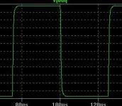
And what do you call a typical "HF input filter"? Attached below is the overshoot reduction of an ideal(ish) 1MHz ULGF TPC (200kHz corner) amp with a 390kHz single pole input filter.
At a 200kHz f3 for the input filter the step response visually returns to RC-like.
Seems a small trade off for the potential gains in an otherwise properly implemented TPC amplifier.
Cheers,
Glen
Attachments

Let's use a 1uHz LP filter, no noise, no distortion neither overshoot at all.
Anyhow, it's a stopgap that hides bad practice. period.
Anyhow, it's a stopgap that hides bad practice. period.
What's the real goal? To make the i/o response not show overshoot...or is it to stop the feedback loop(s) ringing? An i/p filter will do one but not the other. An output inductor will change the phase shift of the load so as to improve the stability of the feedback loop(s) - (in theory, sometimes).

Edmond Stuart said:Let's use a 1uHz LP filter, no noise, no distortion neither overshoot at all.
Anyhow, it's a stopgap that hides bad practice. period.
🙄
We don't need to go quite as low as 1uHz. Here is what it looks like at 300kHz. I don't know about you, but I can't see too much overshoot there.
Attachments
Re: TMC vs TPC
Hi Edmond,
You are largely correct about the closed-loop transient response when using TPC, and I did not forget about that, but rather chose not to touch on that point.
The amount of overshoot depends a lot on the details of the TPC rolloff shape, so broad statements about what it does to the transient response may just lead to a bunch of arguing.
TPC is just a very rough approximation to Bode's ideal 9 dB/octave rolloff. I don't remember the details of his work, but I think I recall that the ideal 9 dB/octave roll-off gave good transient response as well.
Cheers,
Bob
Edmond Stuart said:
Hi Bob,
Only 'a gut of feeling'? I'm afraid you have overlooked one important aspect and I'm pretty sure you know it very well.
Concerning TPC, the steep roll-off and the accompanying phase dip somewhere between 10...100kHz results in overshoot of the step response, typically more than 10%. Of course we don't like this and it seems to me that the only way to get rid it, apart from bluntly masking it by means a LP filter in front of the input, is putting a cap or a series R-C across global NFB resistor. Now, what have we gained by this exercise? Nothing, as this additional phase compensation thingie increases the ULG frequency of the global FB loop considerably.
Apart from stability issues which will certainly arise, probably the same amount of distortion reduction would be accomplished by simply increasing the ULGF without all that TPC hassle. In this regard, TPC is nothing more than putting the cart before the horse.
Needless to say that TMC hasn't this kind of issues.
Cheers,
Edmond.
Hi Edmond,
You are largely correct about the closed-loop transient response when using TPC, and I did not forget about that, but rather chose not to touch on that point.
The amount of overshoot depends a lot on the details of the TPC rolloff shape, so broad statements about what it does to the transient response may just lead to a bunch of arguing.
TPC is just a very rough approximation to Bode's ideal 9 dB/octave rolloff. I don't remember the details of his work, but I think I recall that the ideal 9 dB/octave roll-off gave good transient response as well.
Cheers,
Bob
Re: Re: TMC vs TPC
Nobody here is arguing. Period.
Bob Cordell said:about what it does to the transient response may just lead to a bunch of arguing.
Nobody here is arguing. Period.
Not me, sir. 
There seems to be an important question or two here.
1) Does it matter if the TPC circuit overshoots?
2) If it does, then does filtering out HF from the input stop it mattering?
There seems to be an important question or two here.
1) Does it matter if the TPC circuit overshoots?
2) If it does, then does filtering out HF from the input stop it mattering?
Re: Re: Re: TMC vs TPC
LOL! Not even a smiley?
I look at the TPC overshoot thing in this way. This assumes it's done in the front end of an amp. Seems like the CFB OPS situation might be different but I'm not prepared to say.
Anyway, if you express the open-loop gain A(s) as a ratio of polynomials N(s)/D(s), then compute A(s)/(1 + BA(s)), you'll get N(s)/(D(s) + BN(s)). N(s) represents the open-loop zero of the TPC. One way of looking at this is that the feedback moves the poles but can't budge the zeros. So the closed-loop zero will be at around 1/5 to 1/10 the ULG freq, whatever the designer chooses (same frequency as the open-loop zero). The closed-loop poles will of course be somewhere around the ULG freq. For the closed-loop amp, you end up with a negative real axis zero at a frequency much less than the closed-loop poles, and this will usually give overshoot. Putting an input LPF whose pole is the same frequency as the open-loop zero will always eliminate the overshoot, but it also seems to work with the LPF pole at a frequency somewhat greater. I guess it's getting some help from the other closed-loop poles.
G.Kleinschmidt said:Nobody here is arguing. Period.
LOL! Not even a smiley?
I look at the TPC overshoot thing in this way. This assumes it's done in the front end of an amp. Seems like the CFB OPS situation might be different but I'm not prepared to say.
Anyway, if you express the open-loop gain A(s) as a ratio of polynomials N(s)/D(s), then compute A(s)/(1 + BA(s)), you'll get N(s)/(D(s) + BN(s)). N(s) represents the open-loop zero of the TPC. One way of looking at this is that the feedback moves the poles but can't budge the zeros. So the closed-loop zero will be at around 1/5 to 1/10 the ULG freq, whatever the designer chooses (same frequency as the open-loop zero). The closed-loop poles will of course be somewhere around the ULG freq. For the closed-loop amp, you end up with a negative real axis zero at a frequency much less than the closed-loop poles, and this will usually give overshoot. Putting an input LPF whose pole is the same frequency as the open-loop zero will always eliminate the overshoot, but it also seems to work with the LPF pole at a frequency somewhat greater. I guess it's getting some help from the other closed-loop poles.
Re: Re: Re: Re: TMC vs TPC
Scratch that. One of the closed-loop poles must be near the closed-loop zero in order to get flat midband frequency response. The other must be near the ULG freq.
This is a lot like the 1970s era high-speed op-amps that used feedforward compensation, creating a pole-zero "doublet" at midband in the cloed-loop frequency response. There was a classic article back then about the impact of this on settling time, but for the life of me I can't remember who wrote it or its title.
andy_c said:The closed-loop poles will of course be somewhere around the ULG freq.
Scratch that. One of the closed-loop poles must be near the closed-loop zero in order to get flat midband frequency response. The other must be near the ULG freq.
This is a lot like the 1970s era high-speed op-amps that used feedforward compensation, creating a pole-zero "doublet" at midband in the cloed-loop frequency response. There was a classic article back then about the impact of this on settling time, but for the life of me I can't remember who wrote it or its title.
Re: Re: TMC vs TPC
Hi Bob,
As it appears, it was a wise decision of you to NOT touch on that point. 😉
Cheers,
Edmond.
Bob Cordell said:Hi Edmond,
You are largely correct about the closed-loop transient response when using TPC, and I did not forget about that, but rather chose not to touch on that point.
The amount of overshoot depends a lot on the details of the TPC rolloff shape, so broad statements about what it does to the transient response may just lead to a bunch of arguing.
TPC is just a very rough approximation to Bode's ideal 9 dB/octave rolloff. I don't remember the details of his work, but I think I recall that the ideal 9 dB/octave roll-off gave good transient response as well.
Cheers,
Bob
Hi Bob,
As it appears, it was a wise decision of you to NOT touch on that point. 😉
Cheers,
Edmond.
stopgap
Admittedly, 1uHz is overshoot in his own right 😉
To be serious, with your LP filter the overshoot is indeed invisible, but normally, a typical input filter consists of 100 Ohms and 470pF or so. In that case the overshoot is still present. Lowering Fc may creates other problems: a higher R creates more noise and a larger cap may compromise the pre-amp.
Still, I insist it's a stopgap. Masking the overshoot is not the same as removing the cause of it. It is not the overshoot itself that we don't like, instead, it's an indication that somewhere in the system an instability exists (caused that phase dip). You can't remedy this with a 'outboard' LP filter.
BTW, didn't you use TMC as well, did you?
G.Kleinschmidt said:🙄
We don't need to go quite as low as 1uHz. Here is what it looks like at 300kHz. I don't know about you, but I can't see too much overshoot there.
Admittedly, 1uHz is overshoot in his own right 😉
To be serious, with your LP filter the overshoot is indeed invisible, but normally, a typical input filter consists of 100 Ohms and 470pF or so. In that case the overshoot is still present. Lowering Fc may creates other problems: a higher R creates more noise and a larger cap may compromise the pre-amp.
Still, I insist it's a stopgap. Masking the overshoot is not the same as removing the cause of it. It is not the overshoot itself that we don't like, instead, it's an indication that somewhere in the system an instability exists (caused that phase dip). You can't remedy this with a 'outboard' LP filter.
BTW, didn't you use TMC as well, did you?
Re: stopgap
OK, who's typical input filter is that? ~300kHz seems pretty reasonable to me and at least provides some substantial attenuation to RF towards the higher end of the AM broadcast band. I think that this is TPC overshoot is a relatively minor trade-off if dealt with properly, but each to their own
BTW, what about TIM? We "mask" that by filtering the input too don't we?
Cheers,
Glen
Edmond Stuart said:
Admittedly, 1uHz is overshoot in his own right 😉
To be serious, with your LP filter the overshoot is indeed invisible, but normally, a typical input filter consists of 100 Ohms and 470pF or so. In that case the overshoot is still present. Lowering Fc may creates other problems: a higher R creates more noise and a larger cap may compromise the pre-amp.
Still, I insist it's a stopgap. Masking the overshoot is not the same as removing the cause of it. It is not the overshoot itself that we don't like, instead, it's an indication that somewhere in the system an instability exists (caused that phase dip). You can't remedy this with a 'outboard' LP filter.
BTW, didn't you use TMC as well, did you?
OK, who's typical input filter is that? ~300kHz seems pretty reasonable to me and at least provides some substantial attenuation to RF towards the higher end of the AM broadcast band. I think that this is TPC overshoot is a relatively minor trade-off if dealt with properly, but each to their own
BTW, what about TIM? We "mask" that by filtering the input too don't we?
Cheers,
Glen
Re: Re: stopgap
I'm not reading directly the simmie-boy posts, but seeing your quote and after rolling a few times under the table I can't stop sharing this:
A 1Kohm resistor in the input filter has a Johnson noise of 4nV/rtHz. That is, about 600nV in 20-20KHz. Multiply this by, say, a gain of 30 and you get a nice 18uV (eighteen microvolts) RMS noise voltage at the speaker. That is, a power of 8.1E-13W into 4ohm Boy, this is loud!
One must be pretty short of arguments to think about such :bs:
G.Kleinschmidt said:OK, who's typical input filter is that? ~300kHz seems pretty reasonable to me and at least provides some substantial attenuation to RF towards the higher end of the AM broadcast band. I think that this is TPC overshoot is a relatively minor trade-off if dealt with properly, but each to their own
BTW, what about TIM? We "mask" that by filtering the input too don't we?
I'm not reading directly the simmie-boy posts, but seeing your quote and after rolling a few times under the table I can't stop sharing this:
A 1Kohm resistor in the input filter has a Johnson noise of 4nV/rtHz. That is, about 600nV in 20-20KHz. Multiply this by, say, a gain of 30 and you get a nice 18uV (eighteen microvolts) RMS noise voltage at the speaker. That is, a power of 8.1E-13W into 4ohm
Boy, this is loud! One must be pretty short of arguments to think about such :bs:
Well, I just played around with this a bit in MathCad. I assumed the loop gain AB = K(s + a) / s2. At high enough frequencies, this can be approximated as K/s, so K is approximately the unity loop gain freq in rad/sec. Then calculating AB / (1 + AB), you get:
K(s + a) / (s2 + Ks + Ka)
Picking the ULG freq to be 1 MHz, this gives K = 2 * pi * 1e6. The zero (a) is 2 * pi * 200e3, assuming we set this to 1/5 of the ULG freq. Then the roots of the denominator can easily be found. This gives two poles, at f1 and f2. The results are:
f1 = 276.4 kHz and
f2 = 723.6 kHz
You end up with a zero at 200 kHz, then a pole at 276.4 kHz, then another pole at 723.6 kHz. So you can see how the overshoot happens. Blowing up the frequency response should show a very small shelf near the zero.
Edit: I'm assuming resistive feedback (B = constant)
Now for something completely different.
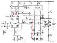
Take that schematic of BC's amplifier attached. Suppose the Miller loop is to be compensated with an RC from the VAS collector to ground instead of as a shunt on the LTP.
Where does the loop gain probe go to investigate the Miller (not the global) loop phase margin? I'm getting results that don't make much sense at the moment.
Cheers,
Glen
Attachments
- Home
- Amplifiers
- Solid State
- Bob Cordell Interview: Negative Feedback