Re: Re: Re: Re: Down with NDFL
Er, that is a bit of a silly semantic evasion. I mean, following this logic we must than say that negative feedback doesn't reduce distortion either.
Also, it is rather relevant exactly how they provide "more loop gain (local and/or global)" because that dictates their effectiveness in different situations.
TMC is a lot more local (OPS only) than either TPC or NDFL.
In theory if the OPS distortion = 0 then the net benefit of TMC = 0.
Not so for TPC or NDFL. This can is easilly demonstrated in SPICE with some pretty simple sims.
syn08 said:
Er, no. TPC, TMC, NDFL, etc... they don't reduce any distortion per se. They just allow more loop gain (local and/or global) to allow the negative feedback to do it's job. The rest is irrelevant.
Er, that is a bit of a silly semantic evasion. I mean, following this logic we must than say that negative feedback doesn't reduce distortion either.
Also, it is rather relevant exactly how they provide "more loop gain (local and/or global)" because that dictates their effectiveness in different situations.
TMC is a lot more local (OPS only) than either TPC or NDFL.
In theory if the OPS distortion = 0 then the net benefit of TMC = 0.
Not so for TPC or NDFL. This can is easilly demonstrated in SPICE with some pretty simple sims.
I think you are both right.
Just for fun. Tell me if this is right.
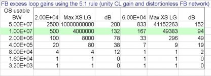
How much excess NFB loop gain is theoretically achievable using the 5:1 rule?
Suppose the usable bandwidth of the raw OS is 10MHz. IOW, 10MHz is the unity loop gain f of the closed loop amp, and suppose the FB network is distortionless.
Max excess loop gain at 20kHz = 10MHz/20kHz x 2MHz/20kHz x 400kHz/20kHz x 80kHz/20kHz = 4 million or 132dB. And the CL amp has unity gain.
Suppose we are interested in THD20 and we are good designers and H3 dominates, then we care about excess loop gain at 60kHz. In this hypothetical case it will be 94dB.
Just for fun. Tell me if this is right.
How much excess NFB loop gain is theoretically achievable using the 5:1 rule?
Suppose the usable bandwidth of the raw OS is 10MHz. IOW, 10MHz is the unity loop gain f of the closed loop amp, and suppose the FB network is distortionless.
Max excess loop gain at 20kHz = 10MHz/20kHz x 2MHz/20kHz x 400kHz/20kHz x 80kHz/20kHz = 4 million or 132dB. And the CL amp has unity gain.
Suppose we are interested in THD20 and we are good designers and H3 dominates, then we care about excess loop gain at 60kHz. In this hypothetical case it will be 94dB.
I see 4 tau's. One for the OPS and the other tau's for a three stage TPC, TMC or whatever. If that's what you mean I think you're right.
Re: Re: Re: Re: Re: Down with NDFL
Given a desired set of loop gain target results, a generic feedback network can be designed, and even worse, the process could be 100% automatized (by synthesis algorithms, and this process is in no way fundamentally different from filter synthesis).
Now, if you think about realisations and down to practical considerations, we may talk about, and here's where Scott comment fits as well. Think in terms of sensitivity rather than network configuration. If you would need a 43.54672pF capacitor and 43.54673 or 43.54671 makes the amp unstable, then the synthesis results are of course useless.
And BTW, NFB won't help for what it doesn't encompass. You and the 1942 CFB inventor, seem to be obsessed with the YAP OPS input stage distortions. Set aside I never said it couldn't be done better (and a new revision is on the board, most likely using Andy's idea) you miss an important point. The YAP OPS compensation main purpose was to a) reduce the MOSFET OPS distortion b) Keep the animal stable and allow as much phase margin. c) Get the ULG as high as possible to avoid interactions with the front end (providing the gain, this is called pole separation). You know the drill from composite opamps... Think of the YAP OPS as the second "opamp" in a composite configuration, and yes, in the next release this opamp will get better!
These three objectives are of course a) not independent and b) not necessary leading to an absolute optimum. For sure integrating the front end with the OPS and extending local loops across both the front end VAS and the OPS will lead to better performance. But what the heck, it was my decision to try and build something that is modular and allowing to experiment with various front end configuration, etc... much as I did with the PGP OPS (accepting three types of output devices and a few compensation configurations). This is DIY and this is the way I am having fun. Other have fun plugging symbols in the simulator and jerking off in front of a bunch of numbers.
G.Kleinschmidt said:Er, that is a bit of a silly semantic evasion.
Given a desired set of loop gain target results, a generic feedback network can be designed, and even worse, the process could be 100% automatized (by synthesis algorithms, and this process is in no way fundamentally different from filter synthesis).
Now, if you think about realisations and down to practical considerations, we may talk about, and here's where Scott comment fits as well. Think in terms of sensitivity rather than network configuration. If you would need a 43.54672pF capacitor and 43.54673 or 43.54671 makes the amp unstable, then the synthesis results are of course useless.
And BTW, NFB won't help for what it doesn't encompass. You and the 1942 CFB inventor, seem to be obsessed with the YAP OPS input stage distortions. Set aside I never said it couldn't be done better (and a new revision is on the board, most likely using Andy's idea) you miss an important point. The YAP OPS compensation main purpose was to a) reduce the MOSFET OPS distortion b) Keep the animal stable and allow as much phase margin. c) Get the ULG as high as possible to avoid interactions with the front end (providing the gain, this is called pole separation). You know the drill from composite opamps... Think of the YAP OPS as the second "opamp" in a composite configuration, and yes, in the next release this opamp will get better!
These three objectives are of course a) not independent and b) not necessary leading to an absolute optimum. For sure integrating the front end with the OPS and extending local loops across both the front end VAS and the OPS will lead to better performance. But what the heck, it was my decision to try and build something that is modular and allowing to experiment with various front end configuration, etc... much as I did with the PGP OPS (accepting three types of output devices and a few compensation configurations). This is DIY and this is the way I am having fun. Other have fun plugging symbols in the simulator and jerking off in front of a bunch of numbers.
Re: Re: Re: Re: Re: Down with NDFL
This was for AC OLG of >>10^6 at very low frequencies.
G.Kleinschmidt said:
Beyond a point wouldn't input offset currents / voltages eventually stop one from any substantial gains?
This was for AC OLG of >>10^6 at very low frequencies.
Re: Down with NDFL
That seems right to me, with one potential caveat. That extra global loop gain you get with TPC has to come from somewhere of course. With TPC, it comes from reducing the local feedback factor of the VAS, thus reducing its local loop gain. If the VAS itself has a substantial contribution to the overall distortion of the amp, as it may in a high-power design, the improvement with TPC might not be as large as expected. TPC does add some extra loading to the VAS as well.
G.Kleinschmidt said:I've been doing some thinking about this while shopping for my groceries. I’ve suddenly become a lot less enamoured with this whole NDFL thingie with the realisation that it is pretty much just TPC.
OK, TPC won’t give you more gain at DC, but so what? To implement TPC you do not have to add additional stages that themselves compromise linearity to a degree and require extensive elaboration to tame overload performance.
That seems right to me, with one potential caveat. That extra global loop gain you get with TPC has to come from somewhere of course. With TPC, it comes from reducing the local feedback factor of the VAS, thus reducing its local loop gain. If the VAS itself has a substantial contribution to the overall distortion of the amp, as it may in a high-power design, the improvement with TPC might not be as large as expected. TPC does add some extra loading to the VAS as well.
Re: Re: Re: Re: Re: Re: Down with NDFL
That's almost correct, I'm born in 1943. 😀
Obsessed? Not at all, only amazed that you have overlooked a significant source of distortion which can easily be avoided.
Now let's get serious. Why setting the ULG as high as possible?
BTW, ULG stands for unity loop gain frequency, so you were talking about the internal CFB loop of the OPS, right?
If you do so (setting the ULGF at 9MHz or so) the OPS itself tend to be unstable. Moreover do we need to set it that high?
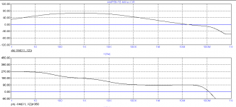
Here some figures from one of my own CFB output stages:
ULGF is much lower: 1.75MHz. Yet the closed loop BW is much higher: -3dB at 22MHz and -45 degrees at 10MHz. At 900kHz, which is the ULGF of the global FB loop, the phase shift is only one degree. So how on earth would this tiny phase shift adversely interact with the front-end?
syn08 said:[snip]
And BTW, NFB won't help for what it doesn't encompass. You and the 1942 CFB inventor,
That's almost correct, I'm born in 1943. 😀
seem to be obsessed with the YAP OPS input stage distortions.
Obsessed? Not at all, only amazed that you have overlooked a significant source of distortion which can easily be avoided.
Set aside I never said it couldn't be done better (and a new revision is on the board, most likely using Andy's idea) you miss an important point. The YAP OPS compensation main purpose was to a) reduce the MOSFET OPS distortion b) Keep the animal stable and allow as much phase margin. c) Get the ULG as high as possible to avoid interactions with the front end (providing the gain, this is called pole separation). You know the drill from composite opamps... Think of the YAP OPS as the second "opamp" in a composite configuration, and yes, in the next release this opamp will get better!
[snip]
Now let's get serious. Why setting the ULG as high as possible?
BTW, ULG stands for unity loop gain frequency, so you were talking about the internal CFB loop of the OPS, right?
If you do so (setting the ULGF at 9MHz or so) the OPS itself tend to be unstable. Moreover do we need to set it that high?
Here some figures from one of my own CFB output stages:
ULGF is much lower: 1.75MHz. Yet the closed loop BW is much higher: -3dB at 22MHz and -45 degrees at 10MHz. At 900kHz, which is the ULGF of the global FB loop, the phase shift is only one degree. So how on earth would this tiny phase shift adversely interact with the front-end?
Re: Re: Down with NDFL
Agreed. On the other hand, TMC doesn't add extra loading. In fact, it unloads the VAS.
andy_c said:That seems right to me, with one potential caveat. That extra global loop gain you get with TPC has to come from somewhere of course. With TPC, it comes from reducing the local feedback factor of the VAS, thus reducing its local loop gain. If the VAS itself has a substantial contribution to the overall distortion of the amp, as it may in a high-power design, the improvement with TPC might not be as large as expected. TPC does add some extra loading to the VAS as well.
Agreed. On the other hand, TMC doesn't add extra loading. In fact, it unloads the VAS.
Re: Re: Re: Down with NDFL
Yup. In fact, what I've noticed in my circuit is that TMC adds a kind of TPC-like effect to the Miller loop gain. IOW, the phase of the Miller loop gain approaches -180 at mid frequencies, then goes back up to around -90 at higher frequencies. Along with that is a -40 dB/dec rolloff in the Miller loop gain over part of the frequency range, but approaching -20 dB/dec as the Miller ULG frequency is reached. Have you seen this?
Edmond Stuart said:Agreed. On the other hand, TMC doesn't add extra loading. In fact, it unloads the VAS.
Yup. In fact, what I've noticed in my circuit is that TMC adds a kind of TPC-like effect to the Miller loop gain. IOW, the phase of the Miller loop gain approaches -180 at mid frequencies, then goes back up to around -90 at higher frequencies. Along with that is a -40 dB/dec rolloff in the Miller loop gain over part of the frequency range, but approaching -20 dB/dec as the Miller ULG frequency is reached. Have you seen this?
Re: Re: Re: Re: Down with NDFL
Let me put it in this way:
For each base amp OL characteristic and given a CL set of performance indicators, there are multiple feedback networks providing exactly the same CL results. Proving this result mathematically is trivial, by reductio ad absurdum and circuit realizability theorems.
Without further considerations (to me, essentially based on sesitivity) any choice can be based strictly on preferences/bias/gender/religion/sexual orientation.
andy_c said:
Yup. In fact, what I've noticed in my circuit is that TMC adds a kind of TPC-like effect to the Miller loop gain. IOW, the phase of the Miller loop gain approaches -180 at mid frequencies, then goes back up to around -90 at higher frequencies. Along with that is a -40 dB/dec rolloff in the Miller loop gain over part of the frequency range, but approaching -20 dB/dec as the Miller ULG frequency is reached. Have you seen this?
Let me put it in this way:
For each base amp OL characteristic and given a CL set of performance indicators, there are multiple feedback networks providing exactly the same CL results. Proving this result mathematically is trivial, by reductio ad absurdum and circuit realizability theorems.
Without further considerations (to me, essentially based on sesitivity) any choice can be based strictly on preferences/bias/gender/religion/sexual orientation.
Or, as the old saying goes, "There are many ways to skin a cat" 🙂. (No offense meant to cat lovers).
Out of interest, just how linear do you guys think you can implement a NDFL stage? This determines how many stages are effective. Is 2 stage, TPC, the practical limit or is ThreePC worth pursuing? It seems to me that 4 stages can fit in the bandwidth available, in theory.
Re: TMC
Hi Andy,
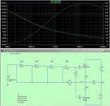
Many times I have also seen such anomalies. BUT putting the gain probe on the right position and disabling the global FB loop (only at the AC level of course), then I get a picture that makes sense, see below.
Regards,
Edmond
andy_c said:Yup. In fact, what I've noticed in my circuit is that TMC adds a kind of TPC-like effect to the Miller loop gain. IOW, the phase of the Miller loop gain approaches -180 at mid frequencies, then goes back up to around -90 at higher frequencies. Along with that is a -40 dB/dec rolloff in the Miller loop gain over part of the frequency range, but approaching -20 dB/dec as the Miller ULG frequency is reached. Have you seen this?
Hi Andy,
Many times I have also seen such anomalies. BUT putting the gain probe on the right position and disabling the global FB loop (only at the AC level of course), then I get a picture that makes sense, see below.
Regards,
Edmond
Attachments
traderbam said:Out of interest, just how linear do you guys think you can implement a NDFL stage? This determines how many stages are effective. Is 2 stage, TPC, the practical limit or is ThreePC worth pursuing? It seems to me that 4 stages can fit in the bandwidth available, in theory.
Not sure I follow your stages enumeration, but to me anything over input stage(no pole)--gain(pole)--gain(pole)--output stage(pole) makes little practical sense. I'm sure an extra gain stage can be accomodated but I doubt its worth the trouble.
andy_c said:Now that you mention it, I believe my probe may be in the wrong place (see below). I'll put it next to C20 and give it another try. I am blocking the global loop gain, so that's not the problem.
Hmm... I don't see why the current position of the gain probe should be wrong.
syn08 said:
Not sure I follow your stages enumeration, but to me anything over input stage(no pole)--gain(pole)--gain(pole)--output stage(pole) makes little practical sense. I'm sure an extra gain stage can be accomodated but I doubt its worth the trouble.
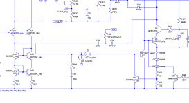
Here's a schematic to illustrate what I'm trying to ask. Here I have created 4 NFB stages, each perfect integrators and each at a 5x GBP interval up to 10MHz. The total excess gain at 20kHz is 132dB and, as you might expect, the THD20 is really tiny...around 500ppb.
The number of stages that can be implemented in practice will be limited, not least, by the THD of the stages, particularly the first stage. So my question is how low a THD do you guys think you could build a stage in practice?
Eg: is -132dB at rated output achievable?
I believe Halcro claim 1000ppb or so.
Brian
Attachments
Re: Re: Down with NDFL
Hi syno8,
I kind of like TMC. I'm not disputing what you are saying, but the fact that the global feedback loop with TMC is still mainly a straight 6 dB/octave rolloff is appealing to me (as compared to TPC, for example).
Bear in mind that in principle one could combine TMC and TPC.
Cheers,
Bob
syn08 said:
And so is TMC or any other three letter acronym 🙂 They all rely on the simple fact that all you need is steep rolloff and proper phase at ULG. So the idea is to insert N poles to get steep roloff then N-1 zeroes to bring the phase back. And space them properly so they don't walk erratically when you close the loop (see the "1/5 ULG rule" in NDFL and the 5:1 cap ratio in TPC).
Hi syno8,
I kind of like TMC. I'm not disputing what you are saying, but the fact that the global feedback loop with TMC is still mainly a straight 6 dB/octave rolloff is appealing to me (as compared to TPC, for example).
Bear in mind that in principle one could combine TMC and TPC.
Cheers,
Bob
- Home
- Amplifiers
- Solid State
- Bob Cordell Interview: Negative Feedback