Hi Edmond,
I didn't pursue this configuration further, since previous experience with my own configuration showed that if the Miller loop wasn't stable I'd get oscillations when the VAS switched into class AB mode in slewing.
Understood. You and I are looking at this from different angles. You're looking at topology comparison in a general sense, and I'm looking at trying to apply those ideas to my specific configuration, with full tweaks, to see if I can improve it.
You're right. I tried this with Frank Wiedmann's version of the loop gain probe, which allows for using both Middlebrook's and Tian's loop gain formulas. Results are absolutely identical out to 100 MHz. I mainly use the Tian approach because I'm lazy and don't want to have to figure out which way to place the probe. Also, there have been a couple of occasions where my convergence is marginal, and one orientation of the probe converges and another does not. And yes, I know that's pretty flaky 🙂.
Regarding the double injection technique with circuit replication, I've attached a graphic of the LTspice way of doing this before the loop gain probe came into common use. I've used it successfully in the past. The current I(V3) is the current going in to the plus side of V3.
So the VAS was definitely unstable, that is, according to the gain/phase response obtained by using the LT gain probe.
But what about the overall performance of the OPS and the behavior of the global NFB loop?
I didn't pursue this configuration further, since previous experience with my own configuration showed that if the Miller loop wasn't stable I'd get oscillations when the VAS switched into class AB mode in slewing.
I have observed the same problem when the output approaches the rail, at least with this circuit. But I have warned you that -to establish a level playing field- the various topologies were not individually tweaked for best performance and stability.
Understood. You and I are looking at this from different angles. You're looking at topology comparison in a general sense, and I'm looking at trying to apply those ideas to my specific configuration, with full tweaks, to see if I can improve it.
BTW, I don't think that omitting the calculation of the reverse-loop transmission is the real cause of my unreliable looking results.
You're right. I tried this with Frank Wiedmann's version of the loop gain probe, which allows for using both Middlebrook's and Tian's loop gain formulas. Results are absolutely identical out to 100 MHz. I mainly use the Tian approach because I'm lazy and don't want to have to figure out which way to place the probe. Also, there have been a couple of occasions where my convergence is marginal, and one orientation of the probe converges and another does not. And yes, I know that's pretty flaky 🙂.
Regarding the double injection technique with circuit replication, I've attached a graphic of the LTspice way of doing this before the loop gain probe came into common use. I've used it successfully in the past. The current I(V3) is the current going in to the plus side of V3.
Attachments

Re: Re: Re: cap
Well there are of course no issues with clipping if the input voltage is limited to several volts below the OPS rails, but I was thinking of the CMCL circuit adapted to the input stage/VAS of a symmetrical power amp, not a unity gain OPS.
Cheers,
Glen
Edmond Stuart said:That 3n3 cap doesn't impair the recovery/performance and in a well designed amp an adequate supply rail decoupling will be necessary anyhow.
Also a nfb VAS clamp has little to with that CMCL 'thingie'.
In the PGP amp a nfb VAS clamp was needed to prevent overcharging of the NDFL caps during clipping, while in the PMP amp a traditional clamp is useless because the OPS has some gain (1.3x) and the front-end has its own (read: independent) power supply.
Well there are of course no issues with clipping if the input voltage is limited to several volts below the OPS rails, but I was thinking of the CMCL circuit adapted to the input stage/VAS of a symmetrical power amp, not a unity gain OPS.
Cheers,
Glen
Hi Glen,
The point is how much is 'several volts'?
For the examples as shown here this margin is about 5V. However, you don't know this in advance, as the margin depends on several factors: load impedance, VGS(th) of the power MOSFETs and in case of a regulated PSU for the front-end but unregulated PSU for the OPS, also on the mains voltage.
So, if you want to stay on the safe you must keep this margin quite large. Much chance that under normal operating condition, the last volts of the OPS stay unutilized. I don't like that.
A FB clamp on the other hand, has not this disadvantage, as it squeezes out the last tens of millivolts from the OPS.
Regards,
Edmond.
Middlebrook
Hi Andy,
Thank you very much for your contribution. It really helped me to find the bugs in the MicroCap macros. Ii and If, respectively Vi and Vf were interchanged. However, the phase is still wrong (inverted), though easily corrected by flipping the sign.
In a simple test circuit I've compared the results with another method, see pg. 12 in: https://www.eecs.berkeley.edu/~boser/courses/240_2004_sp/lectures/L09 lecture.pdf and found identical values. Only above a certain frequency, Tv and Ti slightly deviated, but the final T was still the same.
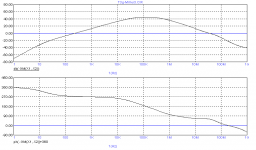
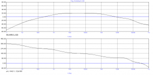
With my debugged macro's I took a closer look at t3g equipped with 10 pair of MOSFTEs. At first, I also saw a wild and frightening response. Nevertheless the amp was (more or less) stable. So I put the probes at a different place et voilà, now I got something that was more in line with my expectations. Not superb, but at least stable (PM=61dgr.), see below. Notice that this amp has not been tweaked for more stability.
So I would ask you where did you put the gain probe? Before R12/R13 (OK) or behind R12/R13 (wrong)?
Regards,
Edmond.
andy_c said:Hi Edmond,
[snip]
Regarding the double injection technique with circuit replication, I've attached a graphic of the LTspice way of doing this before the loop gain probe came into common use. I've used it successfully in the past. The current I(V3) is the current going in to the plus side of V3.
Hi Andy,
Thank you very much for your contribution. It really helped me to find the bugs in the MicroCap macros. Ii and If, respectively Vi and Vf were interchanged. However, the phase is still wrong (inverted), though easily corrected by flipping the sign.
In a simple test circuit I've compared the results with another method, see pg. 12 in: https://www.eecs.berkeley.edu/~boser/courses/240_2004_sp/lectures/L09 lecture.pdf and found identical values. Only above a certain frequency, Tv and Ti slightly deviated, but the final T was still the same.
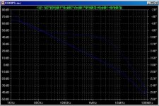
andy_c said:The first configuration I looked at was an adaptation of t3g. This has a current gain of 7x in the Miller loop, and takes the Miller feedback from the emitter of an EF following the VAS. When I looked at the Miller loop gain, I was dismayed by what I saw. At around 10 MHz, its magnitude dropped like a stone, along with the phase. By the time the ULG freq was reached, the phase lag was huge, well in excess of 180 degrees. I gave up on trying to stabilize the thing, because it would have required a compensation cap of thousands of pF together with some careful lead compensation. I'm not sure how Edmond got this stable. His circuit may be an order of magnitude faster than mine, or the phase lag at the ULG freq may have just coincidentally been far from 180 degrees. I don't know. I didn't pursue it further.
With my debugged macro's I took a closer look at t3g equipped with 10 pair of MOSFTEs. At first, I also saw a wild and frightening response. Nevertheless the amp was (more or less) stable. So I put the probes at a different place et voilà, now I got something that was more in line with my expectations. Not superb, but at least stable (PM=61dgr.), see below. Notice that this amp has not been tweaked for more stability.
So I would ask you where did you put the gain probe? Before R12/R13 (OK) or behind R12/R13 (wrong)?
Regards,
Edmond.
Attachments
Re: Middlebrook
Hi Edmond,
My plots were with R12 and R13 as opens. I wanted to see the Miller loop gain without TMC. Previous investigations I did with Miller loop gain of a Blameless configuration with TMC showed that if TMC was properly implemented, it didn't affect GM or PM at all (as expected), but did change the low-frequency Miller loop gain. But I wanted to see the Miller loop gain in its "pure" form without TMC as a start.
This brings up another issue though. As I've mentioned before, when I use the loop gain probe with the Tian formula in only one of the two Miller loops of a complementary design, the simulated loop gain ends up being complete nonsense - something like 0 dB when I know there's tons of loop gain. So joining the two halves of the Miller feedback loop together becomes necessary because there's only one loop gain probe. This is fine when the Miller feedback is taken from the collectors of the VAS and ideal voltage sources are assumed for the bias spreader. But for other configurations, including a non-ideal bias spreader, it's simply impossible to do this without disturbing the circuit (altering impedances, etc.). When taking the feedback from the predriver emitters, I use a kluge and connect both Miller caps to one emitter. This is obviously wrong, but numerically doesn't seem to have too bad of an effect. I've also tried this by joining the two halves of the Miller network together, then inserting the loop gain probe, then coupling to the two predriver emitters with 1 Farad caps. But this is wrong too, as it shorts out the predriver emitter resistors for AC. What to do?
One thing I'd like to try is a variation of Ken Kundert's technique for differential circuits (PDF file). Instead of extracting the difference-mode signal with the ideal balun, the common-mode signal could be extracted instead, thus combining the "tandem" parts of the complementary circuit into one (hopefully) without altering the impedances. The ideal transformer idea is interesting. There was some discussion about it over in the power supplies forum here.
Edmond Stuart said:So I would ask you where did you put the gain probe? Before R12/R13 (OK) or behind R12/R13 (wrong)?
Hi Edmond,
My plots were with R12 and R13 as opens. I wanted to see the Miller loop gain without TMC. Previous investigations I did with Miller loop gain of a Blameless configuration with TMC showed that if TMC was properly implemented, it didn't affect GM or PM at all (as expected), but did change the low-frequency Miller loop gain. But I wanted to see the Miller loop gain in its "pure" form without TMC as a start.
This brings up another issue though. As I've mentioned before, when I use the loop gain probe with the Tian formula in only one of the two Miller loops of a complementary design, the simulated loop gain ends up being complete nonsense - something like 0 dB when I know there's tons of loop gain. So joining the two halves of the Miller feedback loop together becomes necessary because there's only one loop gain probe. This is fine when the Miller feedback is taken from the collectors of the VAS and ideal voltage sources are assumed for the bias spreader. But for other configurations, including a non-ideal bias spreader, it's simply impossible to do this without disturbing the circuit (altering impedances, etc.). When taking the feedback from the predriver emitters, I use a kluge and connect both Miller caps to one emitter. This is obviously wrong, but numerically doesn't seem to have too bad of an effect. I've also tried this by joining the two halves of the Miller network together, then inserting the loop gain probe, then coupling to the two predriver emitters with 1 Farad caps. But this is wrong too, as it shorts out the predriver emitter resistors for AC. What to do?
One thing I'd like to try is a variation of Ken Kundert's technique for differential circuits (PDF file). Instead of extracting the difference-mode signal with the ideal balun, the common-mode signal could be extracted instead, thus combining the "tandem" parts of the complementary circuit into one (hopefully) without altering the impedances. The ideal transformer idea is interesting. There was some discussion about it over in the power supplies forum here.
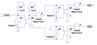
Just for grins, I tried out a variation of Ken Kundert's idea, except it transforms the common-mode voltage of two tandem inputs into a ground-referenced single-ended voltage. I've attached a pic below.
In the graphic, F1, E1 and Vtest1 form a 1:2 (L->R) ideal transformer based on a g matrix representation. The Vtest 0V sources are there only to sample current for the CCCS "F" sources. F2, E2 and Vtest2 have the same function as F1, E1 and Vtest1. At the single-ended side, F3, E3 and Vtest3 form a 1:1 ideal transformer. R1 and R2 prevent DC convergence errors due to floating nodes.
Starting from the right and moving to the left, assume the voltages at sig1 and sig2 are in phase and equal in amplitude. These will be scaled down by a factor of +2 and -2 respectively by the two output transformers. So the common-mode voltage at sig1 and sig2 gets transformed to a difference-mode voltage at the secondary of the input transformer (=0.5*(V(sig1)+V(sig2))). Then the 1:1 transformer at the input converts this difference-mode voltage to a single-ended ground-referenced voltage.
It seems to be working fine so far.
Attachments
66
Hi Andy,
Interesting points, but for a reply you have to wait a couple of days. At the moment I'm rather busy with the preparation of my birthday party.
Till Sunday or so.
Regards,
Edmond.
Hi Andy,
Interesting points, but for a reply you have to wait a couple of days. At the moment I'm rather busy with the preparation of my birthday party.
Till Sunday or so.
Regards,
Edmond.
Re: 66
Hey, I just had my birthday the other week - 32.
And no bulls*&t, my hair is actually getting grey around the ears.
Cheers,
Glen
Edmond Stuart said:Hi Andy,
Interesting points, but for a reply you have to wait a couple of days. At the moment I'm rather busy with the preparation of my birthday party.
Till Sunday or so.
Regards,
Edmond.
Hey, I just had my birthday the other week - 32.
And no bulls*&t, my hair is actually getting grey around the ears.
Cheers,
Glen

Re: Re: Middlebrook
Hi Andy,
Wrong? Kludge? Certainly not. The circuit is symmetrical, so the AC signals at the top and bottom side are essentially identical. Joining two equal signals together by means of a 1F cap or so, doesn't alter the behavior of the circuit. Maybe the common mode properties (i.e. the bias spreader) are it bit affected. So what? In an analysis of the Miller loop, it's only the differential behavior that counts.
Regards,
Edmond.
andy_c said:[snip]
This brings up another issue though. As I've mentioned before, when I use the loop gain probe with the Tian formula in only one of the two Miller loops of a complementary design, the simulated loop gain ends up being complete nonsense - something like 0 dB when I know there's tons of loop gain. So joining the two halves of the Miller feedback loop together becomes necessary because there's only one loop gain probe. This is fine when the Miller feedback is taken from the collectors of the VAS and ideal voltage sources are assumed for the bias spreader. But for other configurations, including a non-ideal bias spreader, it's simply impossible to do this without disturbing the circuit (altering impedances, etc.). When taking the feedback from the predriver emitters, I use a kluge and connect both Miller caps to one emitter. This is obviously wrong, but numerically doesn't seem to have too bad of an effect. I've also tried this by joining the two halves of the Miller network together, then inserting the loop gain probe, then coupling to the two predriver emitters with 1 Farad caps. But this is wrong too, as it shorts out the predriver emitter resistors for AC. What to do?
[snip]
Hi Andy,
Wrong? Kludge? Certainly not. The circuit is symmetrical, so the AC signals at the top and bottom side are essentially identical. Joining two equal signals together by means of a 1F cap or so, doesn't alter the behavior of the circuit. Maybe the common mode properties (i.e. the bias spreader) are it bit affected. So what? In an analysis of the Miller loop, it's only the differential behavior that counts.
Regards,
Edmond.
Re: Re: Re: Middlebrook
Hi Edmond,
I agree that in the analysis of the Miller loop, it's only the common mode that matters (I think that's what you meant). But my goal was to do this without disturbing the circuit. In the normal case of a loop gain probe, say, when looking at the global loop gain, the probe does not affect the circuit one bit. When we need to combine the tandem parts of a complementary circuit, only the common mode signal should be considered and the difference mode should be ignored. But ignoring the difference mode is not the same as shorting it out, as would happen when using 1 F capacitors between emitters when looking at Miller loop gain that's taken from EF emitters.
Ideally, it's a symmetrical circuit, but in practice not perfectly symmetrical, so some difference mode signal will exist. How symmetrical is it out to 100 MHz, where we're simulating the Miller loop gain? Will this have any significant effect? I'm not sure, but my thought was, "better safe than sorry". The purpose of the common mode transformer was to extract the common mode signal while still allowing the difference mode signal (due to asymmetries) to exist.
Edmond Stuart said:Wrong? Kludge? Certainly not. The circuit is symmetrical, so the AC signals at the top and bottom side are essentially identical. Joining two equal signals together by means of a 1F cap or so, doesn't alter the behavior of the circuit. Maybe the common mode properties (i.e. the bias spreader) are it bit affected. So what? In an analysis of the Miller loop, it's only the differential behavior that counts.
Hi Edmond,
I agree that in the analysis of the Miller loop, it's only the common mode that matters (I think that's what you meant). But my goal was to do this without disturbing the circuit. In the normal case of a loop gain probe, say, when looking at the global loop gain, the probe does not affect the circuit one bit. When we need to combine the tandem parts of a complementary circuit, only the common mode signal should be considered and the difference mode should be ignored. But ignoring the difference mode is not the same as shorting it out, as would happen when using 1 F capacitors between emitters when looking at Miller loop gain that's taken from EF emitters.
Ideally, it's a symmetrical circuit, but in practice not perfectly symmetrical, so some difference mode signal will exist. How symmetrical is it out to 100 MHz, where we're simulating the Miller loop gain? Will this have any significant effect? I'm not sure, but my thought was, "better safe than sorry". The purpose of the common mode transformer was to extract the common mode signal while still allowing the difference mode signal (due to asymmetries) to exist.
"better safe than sorry"
Hi Andy,
It may be worth to find out how large the difference is between the 'blunt' method and the 'decent' method, although I wonder how reliable simulations and models are at >100MHz anyhow. If it appears that the difference at frequencies of interest, usually up to 10...20MHz, is rather small, all subsequent sims can be performed using the dirty method.
BTW1, I really hope that the differences are negligible, i.e. no need for Ken Kundert's method, as using a gain probe in MicroCap is already a PITA.
BTW2, Sorry for mixing up common/differential mode. Happily you get message though.
Regards,
Edmond.
Here is my 1st attempt at a CFB OPS, inspired by the YAP.
This is a modified version with a triple EF BJT class A OPS (40W / 4R)
I've simmed the YAP OPS but no matter how hard I try I cannot achieve the claimed 0.002% THD-20 spec. Anyway, I've made some improvements and this version simulates significantly better.
The input stage was a huge source of non-linearity. Not surprising really, as the collector of each input stage trannie basically cops the full signal swing.
THD at 1kHz dropped from >0.001% to ~0.0003% just by adding bootstrapped (Hawksford) cascodes here.
I've also deleted the current mirrors and used a EF-buffered VAS instead. This affords greater loop gain. The EF buffer also effectively minimises distortion due to feedback via cob, allowing the omission of Hawksford cascode's for the VAS transistors (linearity simmed no different with them).
Basic Miller “input” compensation is used ATM instead of TPC and I’ve compensated the Miller loop (not optimised yet).
Comments?
Attachments
Re: CFB OPS
What? No TMC? How dare you? And you peeked at YAP? GTFO!
Seriously, looks good (for a class A 🙂 ). I was planning to cascode the input stage myself, when time comes...
Do R27 and R28 have any significant impact?
G.Kleinschmidt said:loop gain/phase.....
What? No TMC? How dare you? And you peeked at YAP? GTFO!
Seriously, looks good (for a class A 🙂 ). I was planning to cascode the input stage myself, when time comes...
Do R27 and R28 have any significant impact?
G.Kleinschmidt said:...........
The EF buffer also effectively minimises distortion due to feedback via cob, allowing the omission of Hawksford cascode's for the VAS transistors (linearity simmed no different with them).
........................
Comments?
Hint: This also applies to the input stage! Put a diamond buffer in front of the IPS as shown by Andy:
http://www.diyaudio.com/forums/showthread.php?postid=1681713#post1681713
Probably, simple CCSs (instead of cascoded ones) will also do with equal performance. (edit: because Ic of Q26 & Q27 is isolated from the main signal path by means of Q20 & Q24)
Notice that not all Early and Cob effects are eliminated, but low enough to get negligible after global NFB is applied.
Re: Re: CFB OPS
I think Edmond has been peeking at YAP too because now he is playing with CFB output stages 😀
R27 / R28 remove HF peaking in the bootstrapped cascode at a few 10's of MHz. They do no harm and are a safety factor.
I found the bootstrapped cascode works slightly better and the component count is no different. The only thing I would do differently is use 1% voltage references to bias the CCS's to minimise Ic imbalance in the input stage.
Cheers,
Glen
syn08 said:
What? No TMC? How dare you? And you peeked at YAP? GTFO!
Seriously, looks good (for a class A 🙂 ). I was planning to cascode the input stage myself, when time comes...
Do R27 and R28 have any significant impact?
I think Edmond has been peeking at YAP too because now he is playing with CFB output stages 😀
R27 / R28 remove HF peaking in the bootstrapped cascode at a few 10's of MHz. They do no harm and are a safety factor.
Edmond Stuart said:
Hint: This also applies to the input stage! Put a diamond buffer in front of the IPS as shown by Andy:
http://www.diyaudio.com/forums/showthread.php?postid=1681713#post1681713
Probably, simple CCSs (instead of cascoded ones) will also do with equal performance. (edit: because Ic of Q26 & Q27 is isolated from the main signal path by means of Q20 & Q24)
Notice that not all Early and Cob effects are eliminated, but low enough to get negligible after global NFB is applied.
I found the bootstrapped cascode works slightly better and the component count is no different. The only thing I would do differently is use 1% voltage references to bias the CCS's to minimise Ic imbalance in the input stage.
Cheers,
Glen
- Home
- Amplifiers
- Solid State
- Bob Cordell Interview: Negative Feedback