Re: Re: Re: CFB OPS
Scrap that, will have no effect on Ic balance.
G.Kleinschmidt said:to minimise Ic imbalance in the input stage.
Scrap that, will have no effect on Ic balance.
And another thing, no input stage slewing issues.
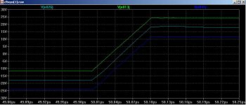
The sim below shows how the collector voltages of the input transistors track the voltage at the junction of the emitter degeneration resistors.
With 5V Vce maintained on the input trannies, low voltage, high speed small-signal types can be used here to further complement the bootstrapped Cob to keep the input impedance really high.
Cheers,
Glen
Attachments
Re: Re: Re: CFB OPS

Yes I did and only that, I have even simmed YAP. The results were beyond all my expectations, that is, in the wrong direction.
With a cap between the emitters of Q26 & Q27 (in Andy's schematic) no issues as well.
I found that too, that is, when I simmed the OPS in isolation. However, when simulating the whole amp (including the front end) it didn't make any difference. If that's also true for your amp, I don't know, as it depends on many details (e.g. distortions from other sources that mask the improvement from the cascode???)
True. But, opposed to your design, if the output trannies and all other stuff are fed from the same supply rails, at the expense of 5V output swing.
Cheers,
Edmond.
edit: The step response (post 2602) looks very good!
G.Kleinschmidt said:.........
I think Edmond has been peeking at YAP too because now he is playing with CFB output stages 😀
.........
Cheers,
Glen
Yes I did and only that, I have even simmed YAP. The results were beyond all my expectations, that is, in the wrong direction.
And another thing, no input stage slewing issues.
With a cap between the emitters of Q26 & Q27 (in Andy's schematic) no issues as well.
I found the bootstrapped cascode works slightly better and the component count is no different.
I found that too, that is, when I simmed the OPS in isolation. However, when simulating the whole amp (including the front end) it didn't make any difference. If that's also true for your amp, I don't know, as it depends on many details (e.g. distortions from other sources that mask the improvement from the cascode???)
With 5V Vce maintained on the input trannies, low voltage, high speed small-signal types can be used here to further complement the bootstrapped Cob to keep the input impedance really high.
True. But, opposed to your design, if the output trannies and all other stuff are fed from the same supply rails, at the expense of 5V output swing.
Cheers,
Edmond.
edit: The step response (post 2602) looks very good!
Re: Re: Re: Re: CFB OPS
You have no grounds to be dissapointed, only your simulator may have some.
Edmond Stuart said:Yes I did and only that, I have even simmed YAP. The results were beyond all my expectations, that is, in the wrong direction.
You have no grounds to be dissapointed, only your simulator may have some
.Re: CFB OPS
What about this:
No further comments. 😛
syn08 said:You have no grounds to be dissapointed, only your simulator may have some
What about this:
Originally posted by G.Kleinschmidt
.........
I've simmed the YAP OPS but no matter how hard I try I cannot achieve the claimed 0.002% THD-20 spec. Anyway, I've made some improvements and this version simulates significantly better.
No further comments. 😛
Re: Re: CFB OPS
I'm ok if that's what your simulators are saying. Honestly I couldn't care less as long as YAP anyway is much better than anything you ever, or will forever, build and listen to.
I understand your frustration, though
What about this:
Just for the heck of it, I have tried your PCP or whatever that monstruosity is currently called on your web site and is totally and irreversible unstable. Again just for the heck of it, I fixed it to my best (I'm not claiming I fully understand that thing) and the performance are dissapointing for the cost and complexity.
No further comments.
Edmond Stuart said:What about this:
No further comments. 😛
I'm ok if that's what your simulators are saying. Honestly I couldn't care less as long as YAP anyway is much better than anything you ever, or will forever, build and listen to.
I understand your frustration, though
What about this:
Just for the heck of it, I have tried your PCP or whatever that monstruosity is currently called on your web site and is totally and irreversible unstable. Again just for the heck of it, I fixed it to my best (I'm not claiming I fully understand that thing) and the performance are dissapointing for the cost and complexity.
No further comments.
Re: Re: Re: CFB OPS
Would you two just get a motel room already.
syn08 said:frustration,
Would you two just get a motel room already.
Re: Re: Re: CFB OPS
That's precisely the trouble with you: you don't understand that 'thing'. You don't even understand why your own YAP equipped with a normal driver was unstable, hence that 'monstrous' diamond thingy.
Anyhow, I strongly advise you: don't build my designs! In your hands it will inevitably lead to a disaster (not to mention on a BB).
BTW: The PMP as well as the MCP amps were only 'design studies' and by now they are obsolete.
syn08 said:..........
Just for the heck of it, I have tried your PCP or whatever that monstruosity is currently called on your web site and is totally and irreversible unstable. Again just for the heck of it, I fixed it to my best (I'm not claiming I fully understand that thing) and the performance are dissapointing for the cost and complexity.
.............
That's precisely the trouble with you: you don't understand that 'thing'. You don't even understand why your own YAP equipped with a normal driver was unstable, hence that 'monstrous' diamond thingy.
Anyhow, I strongly advise you: don't build my designs! In your hands it will inevitably lead to a disaster (not to mention on a BB).
BTW: The PMP as well as the MCP amps were only 'design studies' and by now they are obsolete.
Re: Re: Re: Re: CFB OPS
You wish
Edmond Stuart said:Anyhow, I strongly advise you: don't build my designs!
You wish
Edmond Stuart said:For your own sake (and reputation)
I'm impressed, you really care about?
Anyway, back where you rightfully belong. At least I've tried...
Re: Re: CFB OPS
I'm just reporting on what I found an giving reasons for the modifications I made to the circuit.
After investigating the circuit the YAP was a revelation (to me anyway) as I learnt that with CFB the unity loop gain frequency of the output stage amplifier can approach the inherent -3db frequency pole of the (BJT EF or MOSFET SF) output stage itself.
The whole concept of using NFB to further reduce output stage distortion then suddenly made a lot of sense. And the YAP was a real life circuit showing that it works.
Cheers,
Glen
Edmond Stuart said:
What about this:
No further comments. 😛
I'm just reporting on what I found an giving reasons for the modifications I made to the circuit.
After investigating the circuit the YAP was a revelation (to me anyway) as I learnt that with CFB the unity loop gain frequency of the output stage amplifier can approach the inherent -3db frequency pole of the (BJT EF or MOSFET SF) output stage itself.
The whole concept of using NFB to further reduce output stage distortion then suddenly made a lot of sense. And the YAP was a real life circuit showing that it works.
Cheers,
Glen
The other thing that's interesting about this circuit is that the closed-loop bandwidth is approximately the same as the bandwidth of the driver/output stage combo without feedback, and isn't constrained by the the OPS ULG frequency.
This is kind of stupid, but I think of a figure of merit for the output stage as the bandwidth/distortion ratio. Using CFB in this way doesn't change the bandwidth (at least to a good approximation), yet reduces the distortion. If you took a different, hypothetical case such that you cut the distortion of the open-loop OPS in half, but also cut its bandwidth in half, then when you put the OPS in the feedback loop of the overall amplifier, you'd have to reduce the ULG freq of the overall amplifier by a factor of two to accommodate the OPS bandwidth reduction. But then you'd end up with about the same closed-loop distortion you started with.
All this leads me to conclude that variants of this circuit are the logical successor to EC for ultra-low distortion designs. Still, EC had a pretty darned good run there. Candy felt compelled to use it many years after Bob did 🙂.
andy_c said:If you took a different, hypothetical case such that you cut the distortion of the open-loop OPS in half, but also cut its bandwidth in half, then when you put the OPS in the feedback loop of the overall amplifier, you'd have to reduce the ULG freq of the overall amplifier by a factor of two to accommodate the OPS bandwidth reduction. But then you'd end up with about the same closed-loop distortion you started with.
Exactly!

Cheers,
Glen
Re: Re: Re: CFB OPS
Of course there's plenty of room for improvements, but I was just reporting that I'm not the only one who found a large discrepancy between real and simulated THD.
Also have a look at the theoretical transfer function H(s), which can be found here:
http://www.diyaudio.com/forums/showthread.php?postid=1374791#post1374791
and you will see (after some math) that the closed loop corner frequency (-3dB) can even exceed the -3dB point of the OPS proper.
Suddenly?! I know this already for more than a year. Apparently, you have little faith in (my) simulations.
BTW, my TCP amp does 0.1ppm at 20kHz, full power into 4 Ohm, in spite of using 'nonlinear' MOSFETs in class-AB, an automatic bias generator (no LT6611) and I and V clamps.
Even if the simulation has flattered the THD by a factor of 10, the real THD is still a miniscule 1ppm.
Regards,
Edmond.
G.Kleinschmidt said:I'm just reporting on what I found an giving reasons for the modifications I made to the circuit.
Of course there's plenty of room for improvements, but I was just reporting that I'm not the only one who found a large discrepancy between real and simulated THD.
After investigating the circuit the YAP was a revelation (to me anyway) as I learnt that with CFB the unity loop gain frequency of the output stage amplifier can approach the inherent -3db frequency pole of the (BJT EF or MOSFET SF) output stage itself.
Also have a look at the theoretical transfer function H(s), which can be found here:
http://www.diyaudio.com/forums/showthread.php?postid=1374791#post1374791
and you will see (after some math) that the closed loop corner frequency (-3dB) can even exceed the -3dB point of the OPS proper.
The whole concept of using NFB to further reduce output stage distortion then suddenly made a lot of sense. And the YAP was a real life circuit showing that it works.
Cheers,
Glen
Suddenly?! I know this already for more than a year. Apparently, you have little faith in (my) simulations.
BTW, my TCP amp does 0.1ppm at 20kHz, full power into 4 Ohm, in spite of using 'nonlinear' MOSFETs in class-AB, an automatic bias generator (no LT6611) and I and V clamps.
Even if the simulation has flattered the THD by a factor of 10, the real THD is still a miniscule 1ppm.
Regards,
Edmond.
andy_c said:The other thing that's interesting about this circuit is that the closed-loop bandwidth is approximately the same as the bandwidth of the driver/output stage combo without feedback, and isn't constrained by the the OPS ULG frequency.
This is kind of stupid, but I think of a figure of merit for the output stage as the bandwidth/distortion ratio. Using CFB in this way doesn't change the bandwidth (at least to a good approximation), yet reduces the distortion. If you took a different, hypothetical case such that you cut the distortion of the open-loop OPS in half, but also cut its bandwidth in half, then when you put the OPS in the feedback loop of the overall amplifier, you'd have to reduce the ULG freq of the overall amplifier by a factor of two to accommodate the OPS bandwidth reduction. But then you'd end up with about the same closed-loop distortion you started with.
All this leads me to conclude that variants of this circuit are the logical successor to EC for ultra-low distortion designs. Still, EC had a pretty darned good run there. Candy felt compelled to use it many years after Bob did 🙂.
Hi Andy,
I think this makes a lot of sense. While I'm not sure it spells the end for EC, I think the big take-away message is that fast transistors in the output stage, like MOSFETs, make possible substantial reductions in distortion by local means, whether it is HEC or NFB. I have always stated that the very high ft of the MOSFETs made them a perfect complement to HEC techniques, and this also goes for more conventional local feedback distortion reduction techniques in output stages.
I think that the kind of performance HEC achieved, and the discussions that it fostered, led to a very useful, more unified view of ways to better the output stage by these local means.
If the higher ft of MOSFETs as compared even with RETs makes possible greater use of these local means in the output stage, then this helps make up for some of the increased lower-order distortion of MOSFET output stages that results from their transconductance droop.
Cheers,
Bob
Re: Re: Re: Re: CFB OPS

Edmond Stuart said:
Of course there's plenty of room for improvements, but I was just reporting that I'm not the only one who found a large discrepancy between real and simulated THD.
Also have a look at the theoretical transfer function H(s), which can be found here:
http://www.diyaudio.com/forums/showthread.php?postid=1374791#post1374791
and you will see (after some math) that the closed loop corner frequency (-3dB) can even exceed the -3dB point of the OPS proper.
Suddenly?! I know this already for more than a year. Apparently, you have little faith in (my) simulations.
BTW, my TCP amp does 0.1ppm at 20kHz, full power into 4 Ohm, in spite of using 'nonlinear' MOSFETs in class-AB, an automatic bias generator (no LT6611) and I and V clamps.
Even if the simulation has flattered the THD by a factor of 10, the real THD is still a miniscule 1ppm.
Re: Re: Re: Re: CFB OPS
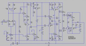
Well with only half as many tricks and a "bare-bones" circuit I'm already down to ~1ppm 50W into 8 ohms and 2ppm 50W into 4 ohms with a single pair of optimally biased (class B) RET's in the output stage.
My very first attempt at ndfl and a evening of playing with the simulator.
This is also a realistic sim - not the kind BS so often seen around here such as ultra low THD but with 1 degree of phase margin (ie only workable in simulator land).
ULG of the ndfl front end is 1MHz. The CFB OPS is 3.5MHz. ~80 degree phase margin and clean squarewaves with no overshoot.
The THD-20, 50W into 8 ohms (28.28V peak):
Harmonic Frequency Fourier Normalized Phase Normalized
Number [Hz] Component Component [degree] Phase [deg]
1 2.000e+04 2.827e+01 1.000e+00 -2.30° 0.00°
2 4.000e+04 2.303e-05 8.149e-07 94.90° 97.20°
3 6.000e+04 1.950e-05 6.899e-07 -136.53° -134.23°
4 8.000e+04 3.238e-06 1.145e-07 -92.86° -90.56°
5 1.000e+05 8.918e-06 3.155e-07 52.96° 55.26°
6 1.200e+05 1.655e-06 5.856e-08 -107.33° -105.03°
7 1.400e+05 6.442e-06 2.279e-07 50.49° 52.79°
8 1.600e+05 3.130e-06 1.107e-07 -115.97° -113.67°
9 1.800e+05 8.567e-06 3.031e-07 39.75° 42.05°
Total Harmonic Distortion: 0.000119%
Schemo:
Edmond Stuart said:
BTW, my TCP amp does 0.1ppm at 20kHz, full power into 4 Ohm,
Well with only half as many tricks and a "bare-bones" circuit I'm already down to ~1ppm 50W into 8 ohms and 2ppm 50W into 4 ohms with a single pair of optimally biased (class B) RET's in the output stage.
My very first attempt at ndfl and a evening of playing with the simulator.
This is also a realistic sim - not the kind BS so often seen around here such as ultra low THD but with 1 degree of phase margin (ie only workable in simulator land).
ULG of the ndfl front end is 1MHz. The CFB OPS is 3.5MHz. ~80 degree phase margin and clean squarewaves with no overshoot.
The THD-20, 50W into 8 ohms (28.28V peak):
Harmonic Frequency Fourier Normalized Phase Normalized
Number [Hz] Component Component [degree] Phase [deg]
1 2.000e+04 2.827e+01 1.000e+00 -2.30° 0.00°
2 4.000e+04 2.303e-05 8.149e-07 94.90° 97.20°
3 6.000e+04 1.950e-05 6.899e-07 -136.53° -134.23°
4 8.000e+04 3.238e-06 1.145e-07 -92.86° -90.56°
5 1.000e+05 8.918e-06 3.155e-07 52.96° 55.26°
6 1.200e+05 1.655e-06 5.856e-08 -107.33° -105.03°
7 1.400e+05 6.442e-06 2.279e-07 50.49° 52.79°
8 1.600e+05 3.130e-06 1.107e-07 -115.97° -113.67°
9 1.800e+05 8.567e-06 3.031e-07 39.75° 42.05°
Total Harmonic Distortion: 0.000119%
Schemo:
Attachments
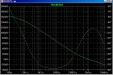
Here is the ndfl loop gain and phase (excluding the CFB OPS).
The Rush current amplifier used as the 1st intergrator is a real limiting factor in this design. I've improved it's linearity a lot by loading it with a CCS (so as not to "cripple" the VAS also) and adding an EF buffer between it and the LTP.
However it still contributes too much distortion and it totally farks the amplifiers overload / transient recovery.
I'll replace this stage with a "VAS" style intergrator next.
Cheers,
Glen
Attachments
- Home
- Amplifiers
- Solid State
- Bob Cordell Interview: Negative Feedback