Mr. Curl
The biggest Cello power amplifier (separated supply monoblocks) is using 2ohm RE, but there are so many output transistors.
Is bigger RE can be compensated with the big ammount of output transistors?
The biggest Cello power amplifier (separated supply monoblocks) is using 2ohm RE, but there are so many output transistors.
Is bigger RE can be compensated with the big ammount of output transistors?
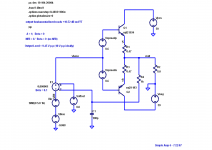
john curl said:Could you try it with .33 ohm and 50ma? That is what my cheapest Parasound design uses.
It looks something like this with 21193/21194, the models do not seem to have fatal error.
Attachments
PMA said:
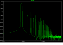
This is "optimal class B bias" (some 47mA) for lowest distortion NUMBER. Though distortion seems low (like 0.02%), its spectrum is horrible. No real NFB can cure it.
Hi Pavel,
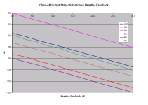
Some of your results and observations are a bit inconsistent with my earlier posts showing simulations of the effect of NFB on a Class-AB output stage.
In my case, I used MJ21193/MJ21194 output transistors with 0.47 ohm RE and over-biased at 152 mA so as to exhibit gm doubling crossover distortion. The load was 8 ohms.
My results are shown below. They show a very well-behaved and predictable reduction in all harmonics as NFB is applied and increased. Note that this was a simulation at 1 kHz and about 10 V p-p into the load.
I wonder if the differences between our results are due to the use of different models or due to my operating into the gm-doubling regime. I did the simulation in the gm doubling regime because I usually prefer to err on the side of over-biasing an output stage (within thermal stability considerations), so gm-doubling distortion is what I am most interested in seeing reduced by NFB.
Cheers,
Bob
Attachments
Bob Cordell said:
Hi Pavel,
Some of your results and observations are a bit inconsistent with my earlier posts showing simulations of the effect of NFB on a Class-AB output stage.
I
Hi Bob,
as I have explained earlier today, I found a significant error in the 2SA1302/2SC3281 models that I used in MC8. So please forget the post (image) you are referring at. The 1st valid simulation of crossover residual should be that of 21193/4 with 0.33 Re into 4 ohms:
http://www.diyaudio.com/forums/showthread.php?postid=1288036#post1288036
Regards,
Pavel
Attachments
PMA, your last graph demonstrates why I like to use high I(q) in my output stage as well, when I can.
What would be REALLY useful is the LOWEST I(q) that we could use and still have VERY LOW 7th harmonic. ONLY very low 7th harmonic is what is necessary here. Everything else can be compromised somewhat. How could we do that?
What would be REALLY useful is the LOWEST I(q) that we could use and still have VERY LOW 7th harmonic. ONLY very low 7th harmonic is what is necessary here. Everything else can be compromised somewhat. How could we do that?
Bob Cordell said:
Hi John,
I agree, 0.47 ohm RE and 50 mA bias is not a very good design, and there are probably too many amplifiers out there with this value. However, I think that the majority of "good" BJT designs are closer to RE = 0.22 ohm and I bias in the range of 100-120 mA.
Cheers,
Bob
I think that many factors besides just the quiescent current of the output stage should be considered when trying to reach a conclusion as to whether or not an amplifier is of good design or not.
There are literally millions of perfectly well engineered and performing BJT-output amplifiers in existence in the 50mA Iq category. A designer may choose to skimp on Iq and use a higher RE for gains in efficiency (resulting in slightly higher crossover distortion) but choose not to roll off their open loop bandwidth for a unity gain cross-over at a meagre 200kHz.
Cheers,
Glen
G.Kleinschmidt said:
There are literally millions of perfectly well engineered and performing BJT-output amplifiers in existence in the 50mA Iq category.
Cheers,
Glen
Hi Glen,
could you, please, mention just one? 😉
Regards,
Pavel
PMA said:
Hi Glen,
could you, please, mention just one? 😉
Regards,
Pavel
Just one? Try about almost any up-market Japanese amplifier with discrete BJT outputs.
Heck, the last high power (~250Wpc) Marantz I repaired ran significantly less than 50mA Iq for each of the paralleled BJT’s. Very nice, well performing design, though I can’t recall the model # off the top of my head ATM.
Cheers,
Glen
PMA said:Hi Bob,
I have modified my 21193/4 circuit to 2 x 50V PSU and 10Vp-p output voltage, 150mA bias. Oops, similar result like your LTspice!
Great!
Bob
You are an easy man to please, Glen. When I got my first Otala based amp in 1975, I got rid of the Marantz 250, Marantz 500, and the SAE. It (the Electrocompaniet) was just that much better sounding. Still sounds good today.
john curl said:PMA, your last graph demonstrates why I like to use high I(q) in my output stage as well, when I can.
What would be REALLY useful is the LOWEST I(q) that we could use and still have VERY LOW 7th harmonic. ONLY very low 7th harmonic is what is necessary here. Everything else can be compromised somewhat. How could we do that?
I do not know how we could do it.
Now the graph for 3.5W/4 ohm. Again, only CFP output stage biased at 900mA. It is all quite fine until we get into AB. Then higher order h. start to rise, and only NFB can decrease them. Which is not the best way to do it.
Attachments
PMA, the whole point is to be in the class AB transistion. Anybody can do OK class A. It is the 7th harmonic generated during the class AB transition that is the MOST important factor to me. It 'may' be that there is an optimum Re to Iq ratio that is not optimum for lowest overall THD, BUT is best for lowest 7th Harmonic distortion for a given Iq. This is where a computer could be very valuable. For example, I usually recommend 15mV-25mV drop across the resistor. However, maybe 35mV gives lowest 7th harmonic distortion at the transistion. I don't know yet. Or, it might be 9mV gives lowest 7th harmonic distortion. Or maybe there is NO 7th harmonic minimum for a given Iq. Who knows?
First thing to find out is how this 7th harmonic get generated in the first place. What happened in the transition between classA and classAB?
- Home
- Amplifiers
- Solid State
- Bob Cordell Interview: Negative Feedback