It looks to me like the intermediate devices are going into saturation, or at least a hard conducting state. While you have them clamped they still are leaving the linear region so the charge in the bases need to be pulled out to get them to respond. Perhaps a Baker clamp would work better at preventing the sticking effect. Its similar to a TTL gate switching. ECL is much faster because it doesn't saturate.
While the current in the compensation circuit is suspicious it may be a symptom not the cause. It may be an effect from the current necessary to kick the followers driving the VAS back into action. Look at the base currents in the various stages for signs of leaving the linear region.
While the current in the compensation circuit is suspicious it may be a symptom not the cause. It may be an effect from the current necessary to kick the followers driving the VAS back into action. Look at the base currents in the various stages for signs of leaving the linear region.
also is a few uSec of sticking really an issue - provided other stages aren't cooking? - its not like you're looking at sub harmonic generation with audio frequency signals
1audio said:It looks to me like the intermediate devices are going into saturation, or at least a hard conducting state. While you have them clamped they still are leaving the linear region so the charge in the bases need to be pulled out to get them to respond. Perhaps a Baker clamp would work better at preventing the sticking effect. Its similar to a TTL gate switching. ECL is much faster because it doesn't saturate.
While the current in the compensation circuit is suspicious it may be a symptom not the cause. It may be an effect from the current necessary to kick the followers driving the VAS back into action. Look at the base currents in the various stages for signs of leaving the linear region.
I can assure you that the sticking is practically entirely due to the LTP compensation cap. Overload recovery is otherwise extremely fast and with traditional miller compensation applied around the VAS the sticking dissapears (as predicted).
You can also increase the value of the LTP cap to over-compensate the miller loop and the sticking time increases entirely proportionally, and is directly correlated to the duration of the charging and discharging current pulses through the LTP cap.
jcx said:also is a few uSec of sticking really an issue - provided other stages aren't cooking? - its not like you're looking at sub harmonic generation with audio frequency signals
Is a slew rate of <100V/us or a THD-20 >0.001% really an issue?
I posted that sim of Bobs amp just to demonstrate how and why the sticking effect exist to some degree with this type of compensation, even when you have a unity loop gain frequency of 2MHz and light miller loop compensation with a JFET input stage. As far as his amp is concerned, I am not going to claim that it is an issue.
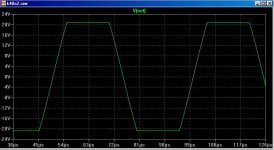
However, as I already stated, I have a ~half the unity loop gain frequency and a BJT input stage with higher gm - that requires heavier miller loop compensation at the LTP and the sticking is much worse (pic attached).
This form of compensation in this application is clealy less than ideal, as far as clipping recovery is concerned.
To put this in perspective, my el-cheapo hybrid, "Blameless" style amp with prehistoric 2N3055/MJ2955 for the output devices clips at 20kHz witout any visible sticking issues:
http://www.diyaudio.com/forums/showthread.php?postid=1488531#post1488531
So any clever suggestions on how to alternatively compensate the miller loop to eliminate the sticking or what?
Cheers,
Glen
Attachments
Ok, here is an alternative compensation method for the fully differential VAS.
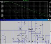
It is a slight deviation from traditional miller compensation applied around the VAS and a depature from Bobs compensation scheme in that the miller loop is no longer returned to the inverting input.
As a consequence the slew rate is not as high, but in this case it is still >100V/us, which is pretty good considering the fact that the unity loop gain frequency is 1MHz, not 2MHz.
A pair of 39 pF miller compensation capacitors are connected between the differential VAS output and one load resistor of each LTP and a pair of 33pF caps shunt compensate the other side of each LTP.
This results in an impeccable loop gain and phase response, as can be seen in the attached pic.......
Attachments

OK, here is the challenge:
Who can work out how I can I get the pristine clipping performance as shown in the post above when setting the unity loop gain frequency with a "miller" cap connected between the VAS collector and the inverting LTP input?
Cheers,
Glen
Clamp
Hi Glen,
Look here for some inspiration: http://home.tiscali.nl/data.odyssey/Clamp1.html
I'm sorry I haven't the time (at the moment) to make this example more in line with your topology. Maybe next year (I'm still busy with the renovation of my apartment).
Merry X-mas.
Cheers, Edmond.
Hi Glen,
Look here for some inspiration: http://home.tiscali.nl/data.odyssey/Clamp1.html
I'm sorry I haven't the time (at the moment) to make this example more in line with your topology. Maybe next year (I'm still busy with the renovation of my apartment).
Merry X-mas.
Cheers, Edmond.
Re: Clamp
Thanks Edmond
It will take me a while to digest your circuit, but the clamp isn't the problem. As you can see in my last post, with different compensation there is no sticking.
The problem is with that compensation capacitor across the differential output of the LTP.
Here is what happens when the amplifier enters clipping:
1) The LTP input is over driven
2) The differential input of the VAS is claimped at approximately 0.6V by one of the back-to-back clamp diodes.
3) The VAS is over driven
4) The LTP compensation capacitor attains a charge of 0.6V
When the amplifier tries to come out of clipping, this capacitor keeps the VAS overdriven for a brief period, causing the sticking that I showed in post 2500:
http://www.diyaudio.com/forums/showthread.php?postid=1693357#post1693357
This puzzled me at first. The LTP with a tail current of 4mA should be able to restore equilibrium with that puny 150pF in the way blisteringly quick, right? Well no, because the bandwidth limitation imposed by the “miller” feedback capacitor and the resultant dv/dt of the error signal makes that an impossibility.
BTW, do you still have Bob's amp in your sim files? If you could quickly run a clipping sim of this amp to verify the behaviour that I showed in post 2500 it would be appreciated! 🙂
BTW, I've been simming TMC on this amp, implemented as in my 12W amp (1MHz ULG and the same transistion frequency) and the results are currently looking hard to beat, as far as this topology goes.
Merry X-mass.
Cheers,
Glen
Edmond Stuart said:Hi Glen,
Look here for some inspiration: http://home.tiscali.nl/data.odyssey/Clamp1.html
I'm sorry I haven't the time (at the moment) to make this example more in line with your topology. Maybe next year (I'm still busy with the renovation of my apartment).
Merry X-mas.
Cheers, Edmond.
Thanks Edmond
It will take me a while to digest your circuit, but the clamp isn't the problem. As you can see in my last post, with different compensation there is no sticking.
The problem is with that compensation capacitor across the differential output of the LTP.
Here is what happens when the amplifier enters clipping:
1) The LTP input is over driven
2) The differential input of the VAS is claimped at approximately 0.6V by one of the back-to-back clamp diodes.
3) The VAS is over driven
4) The LTP compensation capacitor attains a charge of 0.6V
When the amplifier tries to come out of clipping, this capacitor keeps the VAS overdriven for a brief period, causing the sticking that I showed in post 2500:
http://www.diyaudio.com/forums/showthread.php?postid=1693357#post1693357
This puzzled me at first. The LTP with a tail current of 4mA should be able to restore equilibrium with that puny 150pF in the way blisteringly quick, right? Well no, because the bandwidth limitation imposed by the “miller” feedback capacitor and the resultant dv/dt of the error signal makes that an impossibility.
BTW, do you still have Bob's amp in your sim files? If you could quickly run a clipping sim of this amp to verify the behaviour that I showed in post 2500 it would be appreciated! 🙂
BTW, I've been simming TMC on this amp, implemented as in my 12W amp (1MHz ULG and the same transistion frequency) and the results are currently looking hard to beat, as far as this topology goes.
Merry X-mass.
Cheers,
Glen
Hi glen,
>1) The LTP input is over driven.
That's precisely the problem. If you can prevent that, all next stages will not be over driven and no sticking will occur. In the PMP amp Q19 detects when the VAS (Q25) becomes saturated (Vce~=0.5V). It then sends a signal back to the inverting input (via D4 and R15). That's the crux.
BTW, the clamp of the PGP amp is based on the same principle.
Here's a link that does work: http://home.tiscali.nl/audio/
And here more details about that clamp: http://home.tiscali.nl/data.odyssey/PGP.html
Regarding Bob's amp, I do have a file, but only in MicroCap format.
Cheers,
Edmond.
Edmond Stuart said:Hi glen,
>1) The LTP input is over driven.
That's precisely the problem. If you can prevent that, all next stages will not be over driven and no sticking will occur. In the PMP amp Q19 detects when the VAS (Q25) becomes saturated (Vce~=0.5V). It then sends a signal back to the inverting input (via D4 and R15). That's the crux.
BTW, the clamp of the PGP amp is based on the same principle.
Here's a link that does work: http://home.tiscali.nl/audio/
And here more details about that clamp: http://home.tiscali.nl/data.odyssey/PGP.html
Regarding Bob's amp, I do have a file, but only in MicroCap format.
Cheers,
Edmond.
OK, I can see where you are coming from now - a negative feedback clamp that works around the whole amplifier.
Cheers,
Glen
G.Kleinschmidt said:I’ve just been optimising the frequency compensation of a preliminary design of mine in which I used the frequency compensation method that Bob Cordell used in his MOSFET power amp. Namely the unity loop gain frequency is set as desired with a “Miller” feedback capacitor from the VAS collector to the inverting input, while this loop, which can be referred to as the Miller loop, is compensated with an R-C loading the LTP.
With my amplifier adequately compensated with a unity loop gain of 950kHz the slew rate was near 150V/us and operation was other wise fine, with the exception of the clipping performance.
A diode clamp is used on the VAS collector, but coming out of clipping there was significant rail sticking that could not be attributed to either the output stage or the VAS.
The cause of the sticking was tracked down to the LTP R-C. The problem here is that when the amplifier has clipped, the LTP has become overdriven and the compensation capacitor at its output attains a charge that must be gotten rid of when the amplifier comes out of clipping. This takes an amount of time, during which the amplifier’s output “sticks”.
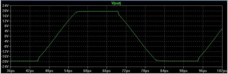
I’ve attached a screen shot of a simplified simulation (I have omitted the cascodes and used an ideal output stage) of Bob’s amplifier to show the sticking effect, clipping at 20kHz.
The VAS is diode clamped at +/-30V. The blue trace is the current through the LTP R-C. The alternate changing and discharging of the compensation capacitance during the sticking period as the amplifier enters and leaves clipping can be clearly seen.
For the LTP R-C, Bobs amplifier used 100 ohms in series with 150pF. I am using a BJT’s for the LTP (instead of JFETs) which have higher gm. For adequate compensation of the miller loop a lower value R and a higher value C is therefore required. The sticking was therefore proportionally worse. While it can be reduced by significantly reducing the LTP’s gm with higher emitter degeneration and lightening the miller loop compensation accordingly, this is not desirable.
I’m now rethinking the compensation scheme for this amplifier. Any ideas on an alternative way to compensate the miller loop that does not cause rail sticking?
Cheers,
Glen
Hi Glen,
I think I agree with your analysis with regard to that implementation of what I refer to as input Miller compensation. The need to compensate the Miller loop does have a cost, and I believe it can have this modest sticking effect you show. It looks like in the case you presented, the sticking interval is about 1 us.
I don't like sticking at all, although this amount and kind of sticking seems more benign that a lot that I've seen, especially when any transistors are allowed to saturate. Of course, sticking will be influenced in different amplifiers depending on whether the VAS or the output stage clips first, and whether or not Baker clamps are used.
I have not looked closely in simulation recently at my MOSFET amplifier to see how much of this type of sticking behavior it exhibits. However, there is no question that your observation about the Miller loop compensating capacitor attaining a charge during clipping that must be dealt with during a sticking interval is true. Its just a matter of how long this interval will be.
This compensation scheme thus does have a cost, but it does also have big benefits in terms of naturally-achievable slew rate (300 V/us in my amp) and the fact that it effectively encloses the input stage in a feedback loop.
In later implementations of my compensation scheme, I've added a series R-C shunting the VAS output node to ground as part of the Miller loop compensation. In some designs this improves the stability of the Miller compensation loop. In some cases, the use of this R-C allows one to decrease the size of the LTP shunt capacitor, reducing the sticking. Another key point to keep in mind is how high the allowable gain crossover frequency for the Miller loop can be. Obviously, the higher we can make it, the smaller need be the capacitance shunting the LTP.
One other thing to bear in mind is whether a resistor is inserted in series with the main Miller compensation capacitor (providing a zero in the open-loop response above the gain crossover frequency). This can have an influence on the necessary compensation for the Miller loop.
BTW, I have also seen really excellent results with TMC. I have also applied TMC back to the LTP inverting input with success.
Cheers,
Bob
Re: TMC
Hi Edmond,
BTW, I seem to recall that when you coined the term TMC for Transitional Miller Compensation, you indicated that Baxandall had actually come up with the scheme. Is that right? If so, is there a reference to Baxandall's work describing it?
Thanks,
Bob
Edmond Stuart said:Hi Bob & Glen,
I'm glad to hear TMC does so well. 😀
Cheers,
Edmond.
Hi Edmond,
BTW, I seem to recall that when you coined the term TMC for Transitional Miller Compensation, you indicated that Baxandall had actually come up with the scheme. Is that right? If so, is there a reference to Baxandall's work describing it?
Thanks,
Bob
Howdy, and merry xmas , Bob C. and others..
As well as you, I dont like "sticking"😡 In fact I lose sleep
over it..😀 I am using fairchild KSA1381/3503 models which
seem to highlight this dreaded errata (mje-xx and BD-xx
don't do it in the same circuit???)
[Evil "sticking"😱 ]
Next is the CM I am using and (hopefully) the cheap fix for it..
I tried to at least reduce it.. not wanting to increase the parts count or complexity of the circuit.. the next
plot is the garbage at the
base of Q6 (saturation ? ) and the diode. Last is the resultant
waveform from a grossly overdriven amp.
I seem to have eliminated it completely at slight clip but the
last plot shows a tiny bit of hang at gross overdrive.
At pre- clip conditions the circuit appears to behave textbook.
Any comments would be highly appreciated..
thanks
OS
Any
By B. cordell..I don't like sticking at all, although this amount and kind of sticking seems more benign that a lot that I've seen, especially when any transistors are allowed to saturate. Of course, sticking will be influenced in different amplifiers depending on whether the VAS or the output stage clips first, and whether or not Baker clamps are used.
As well as you, I dont like "sticking"😡 In fact I lose sleep
over it..😀 I am using fairchild KSA1381/3503 models which
seem to highlight this dreaded errata (mje-xx and BD-xx
don't do it in the same circuit???)
An externally hosted image should be here but it was not working when we last tested it.
[Evil "sticking"😱 ]
Next is the CM I am using and (hopefully) the cheap fix for it..
An externally hosted image should be here but it was not working when we last tested it.
I tried to at least reduce it.. not wanting to increase the parts count or complexity of the circuit.. the next
plot is the garbage at the
base of Q6 (saturation ? ) and the diode. Last is the resultant
waveform from a grossly overdriven amp.
An externally hosted image should be here but it was not working when we last tested it.
An externally hosted image should be here but it was not working when we last tested it.
I seem to have eliminated it completely at slight clip but the
last plot shows a tiny bit of hang at gross overdrive.
At pre- clip conditions the circuit appears to behave textbook.
Any comments would be highly appreciated..
thanks
OS
Any
Bob Cordell said:
Hi Glen,
I think I agree with your analysis with regard to that implementation of what I refer to as input Miller compensation. The need to compensate the Miller loop does have a cost, and I believe it can have this modest sticking effect you show. It looks like in the case you presented, the sticking interval is about 1 us.
I don't like sticking at all, although this amount and kind of sticking seems more benign that a lot that I've seen, especially when any transistors are allowed to saturate. Of course, sticking will be influenced in different amplifiers depending on whether the VAS or the output stage clips first, and whether or not Baker clamps are used.
I have not looked closely in simulation recently at my MOSFET amplifier to see how much of this type of sticking behavior it exhibits. However, there is no question that your observation about the Miller loop compensating capacitor attaining a charge during clipping that must be dealt with during a sticking interval is true. Its just a matter of how long this interval will be.
This compensation scheme thus does have a cost, but it does also have big benefits in terms of naturally-achievable slew rate (300 V/us in my amp) and the fact that it effectively encloses the input stage in a feedback loop.
In later implementations of my compensation scheme, I've added a series R-C shunting the VAS output node to ground as part of the Miller loop compensation. In some designs this improves the stability of the Miller compensation loop. In some cases, the use of this R-C allows one to decrease the size of the LTP shunt capacitor, reducing the sticking. Another key point to keep in mind is how high the allowable gain crossover frequency for the Miller loop can be. Obviously, the higher we can make it, the smaller need be the capacitance shunting the LTP.
One other thing to bear in mind is whether a resistor is inserted in series with the main Miller compensation capacitor (providing a zero in the open-loop response above the gain crossover frequency). This can have an influence on the necessary compensation for the Miller loop.
BTW, I have also seen really excellent results with TMC. I have also applied TMC back to the LTP inverting input with success.
Cheers,
Bob
Thanks Bob.
Adding a zero to both the open loop response and the Miller loop allowed a significant reduction in the required Miller loop copmensation capacitance. I also found that doubling the VAS emitter degeneration was an effective and relatively cost-free way to afford and other ~2:1 reduction.
I've arrived at an all-over compromise that I'm pretty happy with. Unity loop gain frequency (900kHz) and Miller loop compensation is still conservative, the compensated loop phase response is ruler flat and the sticking has been reduced to a pretty neglible level.
Now I just have to redo the PCB layout to incorporate the extra three resistors.
Cheers,
Glen
Attachments

Re: Re: TMC
Hi Bod,
Yes, that's right, that is, Douglas Self told me so. Regrettably, I'm not aware of any publication by Baxandall on this subject. The only thing I know is that D. Self was not 'excited' by using TMC (private communication, many years ago).
Merry X-mas,
Edmond.
Bob Cordell said:Hi Edmond,
BTW, I seem to recall that when you coined the term TMC for Transitional Miller Compensation, you indicated that Baxandall had actually come up with the scheme. Is that right? If so, is there a reference to Baxandall's work describing it?
Thanks,
Bob
Hi Bod,
Yes, that's right, that is, Douglas Self told me so. Regrettably, I'm not aware of any publication by Baxandall on this subject. The only thing I know is that D. Self was not 'excited' by using TMC (private communication, many years ago).
Merry X-mas,
Edmond.
Re: Re: Re: TMC
Wot!!?? 😕
In his book he seems pretty excited about 2-pole compensation 😀
I like TMC better because the resistor tied to the junction of the two compensation capacitors is effectively bootstrapped at HF, reducing its loading effect on the VAS.
Cheers,
Glen
Edmond Stuart said:
Hi Bod,
Yes, that's right, that is, Douglas Self told me so. Regrettably, I'm not aware of any publication by Baxandall on this subject. The only thing I know is that D. Self was not 'excited' by using TMC (private communication, many years ago).
Merry X-mas,
Edmond.
Wot!!?? 😕
In his book he seems pretty excited about 2-pole compensation 😀
I like TMC better because the resistor tied to the junction of the two compensation capacitors is effectively bootstrapped at HF, reducing its loading effect on the VAS.
Cheers,
Glen
G.Kleinschmidt said:
Thanks Bob.
Adding a zero to both the open loop response and the Miller loop allowed a significant reduction in the required Miller loop copmensation capacitance. I also found that doubling the VAS emitter degeneration was an effective and relatively cost-free way to afford and other ~2:1 reduction.
I've arrived at an all-over compromise that I'm pretty happy with. Unity loop gain frequency (900kHz) and Miller loop compensation is still conservative, the compensated loop phase response is ruler flat and the sticking has been reduced to a pretty neglible level.
Now I just have to redo the PCB layout to incorporate the extra three resistors.
Cheers,
Glen
Hi Glen,
Glad to hear of the improvement!
I checked a BJT LTP simulation version of my original IPS-VAS from my MOSFET amplifier, and it exhibited almost 1 us of sticking time.
I then eliminated the R-C at the LTP collectors and compensated the Miller loop using just a series R-C from VAS output to ground. Under those conditions, the sticking time was reduced to about 0.2 us.
Merry Christmas!
Bob
Re: Re: Re: TMC
Thanks Edmond, and Merry Christmas to you as well.
Best,
Bob
Edmond Stuart said:
Hi Bod,
Yes, that's right, that is, Douglas Self told me so. Regrettably, I'm not aware of any publication by Baxandall on this subject. The only thing I know is that D. Self was not 'excited' by using TMC (private communication, many years ago).
Merry X-mas,
Edmond.
Thanks Edmond, and Merry Christmas to you as well.
Best,
Bob
Re: TMC
Hi Glen,
That's exactly what amazed me too! I asked Douglas Self (by e-mail) why he was so enthusiastic about TPC and at the same time got disappointing results with TMC. Regrettably, he didn't (or couldn't) answer me. I guess he doesn't fully understand all aspects of TMC. The point is that it only reduces the distortion of the output stage, while TPC also reduces the distortion of the VAS and input stage. So if the distortion of the latter two are dominating, TMC will do (almost) nothing to improve the performance.
There's one more important point: TMC will only work if there is a sufficient Miller effect, that is, if the gain inside the compensation loop is sufficiently high. IOW, no Miller effect, no transitional Miller compensation.
See also:
http://www.diyaudio.com/forums/showthread.php?postid=1597320#post1597320 ,
http://www.diyaudio.com/forums/showthread.php?postid=1598147#post1598147
and
http://www.diyaudio.com/forums/showthread.php?postid=1613482#post1613482
As you can see, there are many ways to make TMC 'unexciting'.
Indeed, opposed to TPC, no loading of the VAS.
Cheers,
Edmond.
G.Kleinschmidt said:Wot!!?? 😕
In his book he seems pretty excited about 2-pole compensation 😀
Hi Glen,
That's exactly what amazed me too! I asked Douglas Self (by e-mail) why he was so enthusiastic about TPC and at the same time got disappointing results with TMC. Regrettably, he didn't (or couldn't) answer me. I guess he doesn't fully understand all aspects of TMC. The point is that it only reduces the distortion of the output stage, while TPC also reduces the distortion of the VAS and input stage. So if the distortion of the latter two are dominating, TMC will do (almost) nothing to improve the performance.
There's one more important point: TMC will only work if there is a sufficient Miller effect, that is, if the gain inside the compensation loop is sufficiently high. IOW, no Miller effect, no transitional Miller compensation.
See also:
http://www.diyaudio.com/forums/showthread.php?postid=1597320#post1597320 ,
http://www.diyaudio.com/forums/showthread.php?postid=1598147#post1598147
and
http://www.diyaudio.com/forums/showthread.php?postid=1613482#post1613482
As you can see, there are many ways to make TMC 'unexciting'.
I like TMC better because the resistor tied to the junction of the two compensation capacitors is effectively bootstrapped at HF, reducing its loading effect on the VAS.
Cheers,
Glen
Indeed, opposed to TPC, no loading of the VAS.
Cheers,
Edmond.
- Home
- Amplifiers
- Solid State
- Bob Cordell Interview: Negative Feedback