Indeed.janneman said:Nice! I like it when everything is made as simple as possible, but not simpler, to quote Mr. Einstein (I think).
In my sims, performance is identical, except for input Z.I don't intuitively see immediately what the performance difference is between the two. C2/C4 being as large as they are, I would *suspect* but don't kill me for it, that the performance is pretty similar.
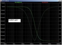
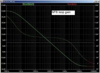
Yes, that is the trade-off between stability and NFB loop gain. In the circuits show (which are only approximations to PAX) the NFB unity gain f is about 200kHz. 150/5 is 30, so your performance difference corresponds closely to the NF loop gain.That C2/C4 at 150pF is determining the final ec in the paX amp. On my test bench I had it working with just 36pF, and the ec was at least 5x better, but I couldn't get it unconditionally stable with cap loads, so in the interest of stability margin I went for 150pF.
These caps are like Miller caps. They set the first pole frequency. So if you make them 15pF the ULG f rises to about 2MHz.I guess you simmed these, can you show us the beef please?
As shown I guess it is stable without C2/C4; how does it look without these caps?
I'll post the simulator results...
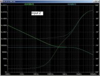
Input Z for figs A and B. Here, fig A has a fairly flat impedance of 50k-ohms up to about 2MHz. Fig B has a rising impedance with decreasing frequency.
You'll observe that C4 does not need to be connected to Vin. I did this just to make the circuits look similar. If C4 is connected to gnd, then the input Z of Fig B is infinite. In practice, it will be the i/p Z of the AD844, increased by the NFB.
You'll observe that C4 does not need to be connected to Vin. I did this just to make the circuits look similar. If C4 is connected to gnd, then the input Z of Fig B is infinite. In practice, it will be the i/p Z of the AD844, increased by the NFB.
Attachments
Brian,
Sorry for the late reply; I thought there were no more posts after you posting A & B, just now found that you actually did also post the curves. I'll need to study them.
Thanks,
Jan Didden
Sorry for the late reply; I thought there were no more posts after you posting A & B, just now found that you actually did also post the curves. I'll need to study them.
Thanks,
Jan Didden
Brian,
A question to your circuits in your earlier post. What is the reason you used a CS for the plant, and why are the returns of the active elements connected to Vout rather than to ground?
(I am trying to recreate your graphs on my Labcenter Prospice but have issues with convergence).
Jan Didden
A question to your circuits in your earlier post. What is the reason you used a CS for the plant, and why are the returns of the active elements connected to Vout rather than to ground?
(I am trying to recreate your graphs on my Labcenter Prospice but have issues with convergence).
Jan Didden
I have used a transconductance element as a simplification of the darlingtons & emitter resistors you used in your PAX article. I set the transconductance to 1 out of habit, but on reflection it is more accurate to set it higher, depending upon the idle current of the darlingtons. A value of 10 may be more appropriate; you can make it 10 or more but it doesn't affect the curves much.janneman said:A question to your circuits in your earlier post. What is the reason you used a CS for the plant,
I believe I have copied your circuit topology accurately. If I haven't I'll correct it. Your AD844 psu is connected to Vout...the FB circuit is floating on Vout, right?and why are the returns of the active elements connected to Vout rather than to ground?
Finally got some more time to look at this.
Brian, your last posts are quite convincing. Can't find anything wrong with it. Changing the OPS from a TC stage to a VA stage changes the curves, but still in both cases they remain identical.
Changing the OPS gain away from exactly 1 reveals a small correction voltage and a small deviation from zero error because of the finite gain of the AD844, but again in both cases (NFB and Hec) identical (which was to be expected with identical loop gain, but still.).
Seems that when you have a packet of gain, it's doen't make a difference where in the loop you distribute it. I know, I know, another generalization, let it go, I'm just thinking out loud 😉
In wonderfull hindsight, I marvel that theory and reality again cover each other exactly. The theory predicted (although I saw it differently initially) that they should be identical, and reality conforms. Or vice versa? If I may continue OT, it reminds me of what I've read in several places, (I think last in Douglas Hofstatter's book "I am a strange loop" ) about the nature of mathematics. Is mathematics a human invention we constructed to explain reality, doing a great job at it. Or is mathematics an innate attribute of the mesh of physical reality, and have we just discovered it (and are still discovering it)?
Sorry for the OT rant. I must go to work on my new invention. 'Regressive gain partitioning', the best thing since NFB! 😉
Brian (and Edmond and Bob) thanks for the education.
Jan Didden
Hi Jan,
You should see the snow here! We had about 4cm overnight...very unusual for England and is considered a major weather event! Everything looks pretty and clean and bright.
That's right, in essence 🙂. The implementation may afford pros and cons depending upon what voltage or current changes more at which node and so on; different nodes being more or less reactive and more or less linear. The important insight is that it is the excess loop gain that does the work.
I'm looking forward to that! I happen to think that maths is a human invention for modelling reality. Because reality has basic rules...like inertia and springiness and mass and resistance...the maths usually predicts consistently. But I get nervous when people extrapolate the maths and make absurd predictions about reality...like time travel. Quantum observations quickly sober us up again and remind us that we sometimes need to modify the math! Then again, we are reality ourselves, and we invented maths so I suppose maths is reality in a way. I'd better have more coffee.
Thank you too. Your PAX circuit has sparked my interest in CFB op-amps and ground-referenced miller capacitors.
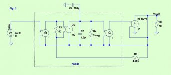
I don't know whether you have the time or inclination to try this, but I would be interested in whether changing your PAX to the conventional FB makes a difference to its sound. Fig C is the arrangement I mean, and it is only a few solder joints different. At the simple simulation level, Fig C should be slightly better because the preceding stage sees a much higher input Z. But reality may be different.
Brian

You should see the snow here! We had about 4cm overnight...very unusual for England and is considered a major weather event! Everything looks pretty and clean and bright.
janneman said:Seems that when you have a packet of gain, it's doen't make a difference where in the loop you distribute it. I know, I know, another generalization, let it go, I'm just thinking out loud 😉
That's right, in essence 🙂. The implementation may afford pros and cons depending upon what voltage or current changes more at which node and so on; different nodes being more or less reactive and more or less linear. The important insight is that it is the excess loop gain that does the work.
In wonderfull hindsight, I marvel that theory and reality again cover each other exactly. The theory predicted (although I saw it differently initially) that they should be identical, and reality conforms. Or vice versa? If I may continue OT, it reminds me of what I've read in several places, (I think last in Douglas Hofstatter's book "I am a strange loop" ) about the nature of mathematics. Is mathematics a human invention we constructed to explain reality, doing a great job at it. Or is mathematics an innate attribute of the mesh of physical reality, and have we just discovered it (and are still discovering it)?
Sorry for the OT rant. I must go to work on my new invention. 'Regressive gain partitioning', the best thing since NFB! 😉
I'm looking forward to that! I happen to think that maths is a human invention for modelling reality. Because reality has basic rules...like inertia and springiness and mass and resistance...the maths usually predicts consistently. But I get nervous when people extrapolate the maths and make absurd predictions about reality...like time travel. Quantum observations quickly sober us up again and remind us that we sometimes need to modify the math! Then again, we are reality ourselves, and we invented maths so I suppose maths is reality in a way. I'd better have more coffee.
Brian (and Edmond and Bob) thanks for the education.
Thank you too. Your PAX circuit has sparked my interest in CFB op-amps and ground-referenced miller capacitors.
I don't know whether you have the time or inclination to try this, but I would be interested in whether changing your PAX to the conventional FB makes a difference to its sound. Fig C is the arrangement I mean, and it is only a few solder joints different. At the simple simulation level, Fig C should be slightly better because the preceding stage sees a much higher input Z. But reality may be different.
Brian
Attachments
Please let me know the currently weblinks - Best thanks.
Tank you very much for the PDF files.
regarded text information this online archive is often very helpful, but not in all cases there are to find the no longer exist websites; unfortunately in most cases there are no photos (image files like jpg)
Please let me know the currently weblinks - Best thanks.
 Put Bob Cordell into Google and see what happens!
Too many proposals. Currently URL is follow:
http://jipihorn.free.fr/Documents/Divers Blog/Cordellinterview.pdf
Indeed, he even complains about the "need" for a pot in HEC designs. I don't know if any of his products use this later approach.
Cheers,
Bob
That's why it is better to use a diff stage for error-correction rather than a single transistor as in HEC. This isolates biasing from the error correction circuitry and makes the use of a pot redundant.
Last edited:
The handoff accomplished by bipolars is more abrupt and may be accompanied by charge-storage artifacts.
Cheers,
Bob
Depends on the type of output stage used. The Locanthi type output stage gets the best out of bipolars and is excellent for EC.
Last edited:
That's why it is better to use a diff stage for error-correction rather than a single transistor as in HEC. This isolates biasing from the error correction circuitry and makes the use of a pot redundant.
I think there are some patents using diff stage for EC from japanese origin. Do other examples exist ?
- Home
- Amplifiers
- Solid State
- Bob Cordell Interview: Error Correction