janneman said:I think it was Brian who remarked that moving the pos fb pickup point after N and then scaling it by 1/N was not allowed as it presumed a linear time-invariant system, which N generally is not.
OTOH, generations of control engineers have been using Laplace transforms to analyse similar systems, although the Laplace transform also presumes a linear, time-invariant system. People who convolve input signals with impulse responses to get output signals also seem to gloss over the fact that their systems are not linear.
So, I was wondering what this means. Does that mean that there is a small deviation from what the math predicts and what the real system gives, depending on how non-linear the system actually is? I could live with that, just like said generations of control engineers 😉
The reason they can live with linear maths is that they are not in the audio amplifier business!
 Most of control theory is about speed and settling time rather than THD. There are methods, like describing functions, which deal with gross non-linearities in the context of settling time and stability. A THD of 1% is normally quite acceptable in most fields, but in audio a THD 2 or 3 orders or magnitude better is the goal. So this leaves it up to us audio enthusiasts to extend the standard theories to account for small non-linearities. And I am afraid that non-linear control theory is very, very difficult indeed.
My general advice is just to be careful not to get into the habit of assuming a system's performance can be accurately represented by a linear approximation. It is fine to do this to get the basics right, but for ultimate fidelity it is important to think deeper.
Re: HEC is positive feedback on demand
This is an interesting example you give. If I have understood your description, you are talking about a bootstrap arrangement - where the voltage change across the non-linear sense resistor is added to the input of the output follower.
I think this is akin to Jan's diagram C. Because you have assumed an element exists that exactly mimics the plant, there is no requirement for huge excess gain. Instead, the exact error is added back to the input in a pre-distortion sort of manner (assuming there are no time delays).
I think your analogy represents the intended behaviour of HEC in the case where stable, infinite excess gain is assumed. You are right to question its usefulness for considering stability.
Bob Cordell said:Here is a version of the feedback-on-demand view of HEC.
With a slight chuckle, I am throwing this into the mix just to create more confusion.
<snip>
This is an interesting example you give. If I have understood your description, you are talking about a bootstrap arrangement - where the voltage change across the non-linear sense resistor is added to the input of the output follower.
I think this is akin to Jan's diagram C. Because you have assumed an element exists that exactly mimics the plant, there is no requirement for huge excess gain. Instead, the exact error is added back to the input in a pre-distortion sort of manner (assuming there are no time delays).
I am not claiming that this view of HEC (positive feedback on demand) is one that provides good insight on stability. Indeed, it may provide a misleading view on stability. For example, if the loop-gain-on-demand is so small, be it positive or negative, how can we possibly get into stability trouble. Maybe I am missing something here. I’m just throwing this all out as a brain teaser.
I think your analogy represents the intended behaviour of HEC in the case where stable, infinite excess gain is assumed. You are right to question its usefulness for considering stability.
Re: Re: HEC is positive feedback on demand
Hi Brian, indeed you are right, although I probably would not use the bootstrap term. This is one of the ways I have always looked at HEC.
For some wierd reason, it kind of reminds me of an articulating windshield wiper. I know the analogy is probably flawed.
Cheers,
Bob
traderbam said:
This is an interesting example you give. If I have understood your description, you are talking about a bootstrap arrangement - where the voltage change across the non-linear sense resistor is added to the input of the output follower.
Hi Brian, indeed you are right, although I probably would not use the bootstrap term. This is one of the ways I have always looked at HEC.
For some wierd reason, it kind of reminds me of an articulating windshield wiper. I know the analogy is probably flawed.
Cheers,
Bob
janneman said:Yes, with the caveat that you can almost arbitrarily correct the errors if they appear at lower frequencies. Like in the limiting case at f=0 (DC) you can correct perfectly. That's not a practical use, I concede that.
What I found is that you get the 'nicest' cl response (peaking only 3dB at hf) if you keep the ratio of the BW of the summers and the plant at 1.
Jan Didden
Hi Jan,
Uh... BW(S1) = BW(S2) = BW(K1) or BW(S1+S2) = BW(K1)?
Regards,
Edmond.
Integrator options
A question for Rodolfo,
An integrator can be made using a unity gain buffer, connecting its non-inverting input to its output.
An op-amp is a natural integrator in open loop.
What are the pros and cons of using either? Assume that they have the same unity gain BW.
Brian
A question for Rodolfo,
An integrator can be made using a unity gain buffer, connecting its non-inverting input to its output.
An op-amp is a natural integrator in open loop.
What are the pros and cons of using either? Assume that they have the same unity gain BW.
Brian
Re: Integrator options
Mostly the same.
Making PFB to balance at unity gain basically drives up the gain below the built in dominant pole, which is of doubious interest for audio (except may be subwoofers). It does not change anything beyond it.
I fell in that trap early on, until I noticed simulation in both cases (OpAmp as EC node or simply open loop driver) yielded the same THD, and then it dawned on mi why 😱

Rodolfo
traderbam said:A question for Rodolfo,
An integrator can be made using a unity gain buffer, connecting its non-inverting input to its output.
An op-amp is a natural integrator in open loop.
What are the pros and cons of using either? Assume that they have the same unity gain BW.
Brian
Mostly the same.
Making PFB to balance at unity gain basically drives up the gain below the built in dominant pole, which is of doubious interest for audio (except may be subwoofers). It does not change anything beyond it.
I fell in that trap early on, until I noticed simulation in both cases (OpAmp as EC node or simply open loop driver) yielded the same THD, and then it dawned on mi why 😱
Rodolfo
A different matter is to design a native unity gain buffer with exceptional linearity and bandwidth, and compare with the best available OpAmp.
This is not for me certainly since I consider myself crude in analog design, and anyway for reasons abundantly exposed is mostly a stopgap solution.
Rodolfo
This is not for me certainly since I consider myself crude in analog design, and anyway for reasons abundantly exposed is mostly a stopgap solution.
Rodolfo
Re: Re: Integrator options
🙂 Amusing emoticon sequence!
I suppose one consideration is summer input differential voltage range. With an op-amp, the input difference is going to be very tiny. With the PFB buffer, the input difference will be as large as the voltage swing to the plant...because the buffer only has a gain of 1. So one needs a very linear summer in the face of a relatively wide differential input voltage swing.
ingrast said:I fell in that trap early on, until I noticed simulation in both cases (OpAmp as EC node or simply open loop driver) yielded the same THD, and then it dawned on mi why 😱
🙂 Amusing emoticon sequence!
I suppose one consideration is summer input differential voltage range. With an op-amp, the input difference is going to be very tiny. With the PFB buffer, the input difference will be as large as the voltage swing to the plant...because the buffer only has a gain of 1. So one needs a very linear summer in the face of a relatively wide differential input voltage swing.
Re: Re: Re: Integrator options
That's one reason I used a CCII in my paX amp. Open loop G=1 buffer yet very small diff input signal.
Jan Didden
traderbam said:
🙂 Amusing emoticon sequence!
I suppose one consideration is summer input differential voltage range. With an op-amp, the input difference is going to be very tiny. With the PFB buffer, the input difference will be as large as the voltage swing to the plant...because the buffer only has a gain of 1. So one needs a very linear summer in the face of a relatively wide differential input voltage swing.
That's one reason I used a CCII in my paX amp. Open loop G=1 buffer yet very small diff input signal.
Jan Didden
Edmond Stuart said:
Edmond,
This is what I got with Mathcad trying to get some insight in Hec as to stability. Not very sophisticated, but maybe it is usefull as a start.
Note that I have left the input summer at =1, and varied the fb summer b between 0.9 and 1.1, and K=0.95.
K, b and a are simple first order things with the same -3dB freq.
What I would like to do is vary another variable, like the ratio between -3dB frequencies and produce a 3-d plot like a sheet, but so far I haven't been able to coax Mathcad into doing it....
Comments?
Jan Didden
Attachments
Re: Re: Re: Integrator options
In the OpAmp implementation of the unity gain summing node, you must resort to a network of resistors to make for the gain an summing ratios as required, the tiny differential voltage you refer being the virtual ground, external voltages substantial.
I actually computed, simulated and built an amplifier, with everything checking as expected. Stability could be coped for with basic lead compensation both for a mosfet Szilaky output (posted somewhere here) and for a LM3886 as plant, obtaining excellent results both in measurements and listening (Mosfets doing quite better than the LM3886 and both better than standard LM3886 configuration). Measurement results are also posted somewhere here.
As said, just stripping all the local feedback should have yielded the same results, but did not bother to put it into practice except in simulation.
Actually I have been happily listening for years to my homebuilt electronic crossover 2 way active boxes totalling 4 mosfet output amplifiers of the early type (EC).
Rodolfo
traderbam said:
..I suppose one consideration is summer input differential voltage range. With an op-amp, the input difference is going to be very tiny. ...
In the OpAmp implementation of the unity gain summing node, you must resort to a network of resistors to make for the gain an summing ratios as required, the tiny differential voltage you refer being the virtual ground, external voltages substantial.
I actually computed, simulated and built an amplifier, with everything checking as expected. Stability could be coped for with basic lead compensation both for a mosfet Szilaky output (posted somewhere here) and for a LM3886 as plant, obtaining excellent results both in measurements and listening (Mosfets doing quite better than the LM3886 and both better than standard LM3886 configuration). Measurement results are also posted somewhere here.
As said, just stripping all the local feedback should have yielded the same results, but did not bother to put it into practice except in simulation.
Actually I have been happily listening for years to my homebuilt electronic crossover 2 way active boxes totalling 4 mosfet output amplifiers of the early type (EC).
Rodolfo
Hi Jan.
Looks interesting, but I'm afraid there's still a lot of work to do.
I would suggest the following:
Since the OPS has probably the lowest cut-off frequency and there is little room to change that, it might be interesting to see what happens with a higher ft of S1 and/or S2. Somewhere there must be an optimum with regard to distortion reduction, overall BW and peaking. I realize it's a lot of work, but worth the effort.
BTW, though the peaks are not that large, I'm not really happy with them. If the system is embedded in a complete amp, it might cause troubles.
Good luck,
Edmond.
Edmond Stuart said:Hi Jan.
Looks interesting, but I'm afraid there's still a lot of work to do.
I would suggest the following:
Since the OPS has probably the lowest cut-off frequency and there is little room to change that, it might be interesting to see what happens with a higher ft of S1 and/or S2. Somewhere there must be an optimum with regard to distortion reduction, overall BW and peaking. I realize it's a lot of work, but worth the effort.
BTW, though the peaks are not that large, I'm not really happy with them. If the system is embedded in a complete amp, it might cause troubles.
Good luck,
Edmond.
Well, indeed, if the plant's Fc is (much) lower than that of a or b, peaking increases. If the reverse is true, also. Peaking appears minimal with all Fc's equal.
One solution is to lower a and/or b fc, but that also lowers the error correction of course.
But I'll get there, eventually. I need to look what happens if a, b and K are more realistic with multiple poles etc.
But it's just a matter of imagination and then soldering it all together. Easy, right ? 😀
Jan Didden
Re: Re: Re: Re: Integrator options
Yes, the input voltage difference is kept small by using a current FB op-amp like the AD844. It also helps that the system gain is only 1. You could have used the AD844 in conventional forward gain mode. Did you try this?
janneman said:
That's one reason I used a CCII in my paX amp. Open loop G=1 buffer yet very small diff input signal.
Jan Didden
Yes, the input voltage difference is kept small by using a current FB op-amp like the AD844. It also helps that the system gain is only 1. You could have used the AD844 in conventional forward gain mode. Did you try this?
Re: Re: Re: Re: Re: Integrator options
No I didn't. I didn't want to get into discussions that it did what it did because of some 'hidden' high feedback in the summers ....
Jna Didden
traderbam said:
Yes, the input voltage difference is kept small by using a current FB op-amp like the AD844. It also helps that the system gain is only 1. You could have used the AD844 in conventional forward gain mode. Did you try this?
No I didn't. I didn't want to get into discussions that it did what it did because of some 'hidden' high feedback in the summers ....
Jna Didden
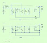
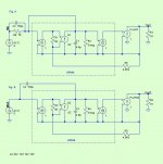
I modified Fig B to correctly include a FB resistor and the 150pF input capacitor.
I present these to facilitate a comparative discussion. Fig 1 is Jan's "PAX implementation of HEC" and Fig 2 is a functionally similar circuit that does not use a PFB loop. Showing the two in stark contrast may help with clarity of understanding.
I am interested in your opinions about the pros and cons of each circuit. What would cause you to favour one over the other?
Brian
Attachments
Nice! I like it when everything is made as simple as possible, but not simpler, to quote Mr. Einstein (I think).
I don't intuitively see immediately what the performance difference is between the two. C2/C4 being as large as they are, I would *suspect* but don't kill me for it, that the performance is pretty similar.
That C2/C4 at 150pF is determining the final ec in the paX amp. On my test bench I had it working with just 36pF, and the ec was at least 5x better, but I couldn't get it unconditionally stable with cap loads, so in the interest of stability margin I went for 150pF.
I guess you simmed these, can you show us the beef please?
As shown I guess it is stable without C2/C4; how does it look without these caps?
Jan Didden
- Home
- Amplifiers
- Solid State
- Bob Cordell Interview: Error Correction