Hi all !!!
Good to see the embers glow again after all this years with just a hint of stirring !!
That HEC is a limiting or - if you like - degenerate case of GNF is something that probably cannot be questioned.
The Error Correction concept as different perspective should neither be banned, just because it turns out to be not different formally. As said, it is a different perspective.
Variations on different topologies as local vs global feedback, or combined, or even frequency dependent variable as TMC, are all tools which as is usually the case must prove in actual implementation - with all the devils implied - their worth.
Rodolfo
I think now that TMC has been popularized (and my thanks to all the guru's here that facilitated that), I wonder it HEC is really worth the effort? On simulation, it is now quite easy to show a decent power amplifer with 1ppm 20K THD at half power using TMC, and under 5ppm at rated output.
We no longer have an issue on getting low distortion. We know how to do it. The question is, how the hell to we build the damn things and still get the result? I think there are only a handfull of people who have demonstrated this practically - Syn08+ES, Bruce Candy and one other guy from Switzerland, but I lost his name. ;-)
We no longer have an issue on getting low distortion. We know how to do it. The question is, how the hell to we build the damn things and still get the result? I think there are only a handfull of people who have demonstrated this practically - Syn08+ES, Bruce Candy and one other guy from Switzerland, but I lost his name. ;-)

Hi all !!!
Good to see the embers glow again after all this years with just a hint of stirring !!
That HEC is a limiting or - if you like - degenerate case of GNF is something that probably cannot be questioned.
The Error Correction concept as different perspective should neither be banned, just because it turns out to be not different formally. As said, it is a different perspective.
Variations on different topologies as local vs global feedback, or combined, or even frequency dependent variable as TMC, are all tools which as is usually the case must prove in actual implementation - with all the devils implied - their worth.
Rodolfo
Hi Rodolfo,
Although HEC can certainly be viewed as a form of negative feedback, I think it is more appropriate to see it as a form of local NFB within the output stage rather than GNFB.
Cheers,
Bob
EC vs NFB
Hi Bob,
Actually, I wasn't thinking of TMC specifically, rather NFB in a more traditional sense.
For example, you might think of the CFB vs HEC output stage as discussed here:
http://www.diyaudio.com/forums/soli...terview-error-correction-282.html#post1356927
BTW, notice how the frequency compensation of the internal loop is established. In both cases (C1 & C2, respectively C10 & C11) they also act as feed forward compensation. This is an important feature, as it degrade the overall performances in a minimal way. Why? Suppose for example, that these caps are way too large, then these output stages still do a reasonable job. Only the corrective signal is damped instead of the whole signal.
Of course, you know this too. But the reason I'm pointing this out (again) is to make clear why the transconductance stage of the LT1166 is virtual useless. This one uses (and needs) shunt compensation, which act on the whole signal. Such compensation wastes gain and loads the signal path unnecessary at higher frequencies. It's a wrong concept.
(Please don't misunderstood me, I'm not talking about the bias generator. That's another story).
Bottom line: avoid shunt compensation whenever possible.
Cheers,
Edmond.
Hi Edmond,
Given what we've learned over the last couple of years, I think it is reasonable to compare the effectiveness of HEC with TMC. I seem to recall in my own experience that TMC was able to produce some really low-distortion amplifiers.
[snip]
Cheers,
Bob
Hi Bob,
Actually, I wasn't thinking of TMC specifically, rather NFB in a more traditional sense.
For example, you might think of the CFB vs HEC output stage as discussed here:
http://www.diyaudio.com/forums/soli...terview-error-correction-282.html#post1356927
BTW, notice how the frequency compensation of the internal loop is established. In both cases (C1 & C2, respectively C10 & C11) they also act as feed forward compensation. This is an important feature, as it degrade the overall performances in a minimal way. Why? Suppose for example, that these caps are way too large, then these output stages still do a reasonable job. Only the corrective signal is damped instead of the whole signal.
Of course, you know this too. But the reason I'm pointing this out (again) is to make clear why the transconductance stage of the LT1166 is virtual useless. This one uses (and needs) shunt compensation, which act on the whole signal. Such compensation wastes gain and loads the signal path unnecessary at higher frequencies. It's a wrong concept.
(Please don't misunderstood me, I'm not talking about the bias generator. That's another story).
Bottom line: avoid shunt compensation whenever possible.
Cheers,
Edmond.
I think now that TMC has been popularized (and my thanks to all the guru's here that facilitated that), I wonder it HEC is really worth the effort? On simulation, it is now quite easy to show a decent power amplifer with 1ppm 20K THD at half power using TMC, and under 5ppm at rated output.
We no longer have an issue on getting low distortion. We know how to do it. The question is, how the hell to we build the damn things and still get the result? I think there are only a handfull of people who have demonstrated this practically - Syn08+ES, Bruce Candy and one other guy from Switzerland, but I lost his name. ;-)
Hi Bonsai, These are good points in viewing HEC vs TMC. I think that if TMC can get us below 0.001% at 20 kHz that is good enough and that HEC may not be worth the extra effort if it can do better than that. I also recognize that some may argue that HEC can not do better than TMC. If HEC can do better than TMC, we may need that extra distortion-reducing capability for some amplifier designs, or it may allow us to relax the design of the output stage in some way.
For example, often MOSFET amplifiers will be more in need of distortion reduction because of their transconductance droop. In fact, this is the biggest reason I employed HEC in my original MOSFET power amplifier with error correction. A fair question, which I have not tried to answer, is whether applying TMC to that amplifier instead of HEC, all else basically the same, would have yielded performance as good.
You are also right in touching on the difficulty of achieving sub-10 ppm distortion numbers in real-world amplifiers, as opposed to amplifiers in simulation. While simulation is extremely important for purposes of comparison and finding/understanding distortion sources, it can at times give optimistic results, and of course it does not include real-world implementation effects like magnetic coupling of nonlinear magnetic fields.
My 50W MOSFET power amplifier, with only a single MOSFET output pair biased at 150mA, came close to your target of 5ppm. It was 6ppm at 50W. Had I used 2 output pair each biased at 150mA it probably would have done better.
Cheers, Bob
Hi Bob,
Actually, I wasn't thinking of TMC specifically, rather NFB in a more traditional sense.
For example, you might think of the CFB vs HEC output stage as discussed here:
http://www.diyaudio.com/forums/soli...terview-error-correction-282.html#post1356927
BTW, notice how the frequency compensation of the internal loop is established. In both cases (C1 & C2, respectively C10 & C11) they also act as feed forward compensation. This is an important feature, as it degrade the overall performances in a minimal way. Why? Suppose for example, that these caps are way too large, then these output stages still do a reasonable job. Only the corrective signal is damped instead of the whole signal.
Of course, you know this too. But the reason I'm pointing this out (again) is to make clear why the transconductance stage of the LT1166 is virtual useless. This one uses (and needs) shunt compensation, which act on the whole signal. Such compensation wastes gain and loads the signal path unnecessary at higher frequencies. It's a wrong concept.
(Please don't misunderstood me, I'm not talking about the bias generator. That's another story).
Bottom line: avoid shunt compensation whenever possible.
Cheers,
Edmond.
Hi Edmond,
I completely agree. The feedforward form of compensation you described was used in my original HEC implementation for that very reason.
I also agree that the transconductance stage in the LT1166 bias controller is relatively useless. That is why I only recommend using it as essentially a replacement for the Vbe multiplier, wherein the necessary compensation for its internal loop also does not affect the open-loop gain.
Cheers,
Bob
Hello Bob
>>My 50W MOSFET power amplifier, with only a single MOSFET output pair biased at 150mA, came close to your target of 5ppm. It was 6ppm at 50W. Had I used 2 output pair each biased at 150mA it probably would have done better.
Have you bettered or equaled this result without using a HEC output stage with an amplifier you have built and tested.
Regards
Arthur
HEC vs TMC
Hi Arthur & Bob,
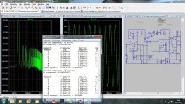
For purpose of comparison here are a few more simulated figures:
Bob's amp with HEC: THD20 = 5.7ppm
Bob's amp with TMC: THD20 = 8.7ppm
without HEC or TMC: THD20 = 96 ppm
As you see, TMC scores not as good as HEC, though it comes close.
I've tried to keep essential parameters as much as possible equal, except one thing: the transition frequency of the TMC network. It has to be limited at 1MHz, opposed to the 3MHz BW of the EC circuitry. If it was also set to 3MHz, the distortion would equal that of HEC, but at the expense of stability which dropped to an unacceptable level.
Cheers,
E.
[snip]
A fair question, which I have not tried to answer, is whether applying TMC to that amplifier instead of HEC, all else basically the same, would have yielded performance as good.
[snip]
My 50W MOSFET power amplifier, with only a single MOSFET output pair biased at 150mA, came close to your target of 5ppm. It was 6ppm at 50W.
[snip]
Cheers, Bob
Hello Bob
>>My 50W MOSFET power amplifier, with only a single MOSFET output pair biased at 150mA, came close to your target of 5ppm. It was 6ppm at 50W. Had I used 2 output pair each biased at 150mA it probably would have done better.
[snip]
Regards
Arthur
Hi Arthur & Bob,
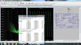
For purpose of comparison here are a few more simulated figures:
Bob's amp with HEC: THD20 = 5.7ppm
Bob's amp with TMC: THD20 = 8.7ppm
without HEC or TMC: THD20 = 96 ppm
As you see, TMC scores not as good as HEC, though it comes close.
I've tried to keep essential parameters as much as possible equal, except one thing: the transition frequency of the TMC network. It has to be limited at 1MHz, opposed to the 3MHz BW of the EC circuitry. If it was also set to 3MHz, the distortion would equal that of HEC, but at the expense of stability which dropped to an unacceptable level.
Cheers,
E.
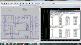
Hi Arthur & Bob,
For purpose of comparison here are a few more simulated figures:
Bob's amp with HEC: THD20 = 5.7ppm
Bob's amp with TMC: THD20 = 8.7ppm
without HEC or TMC: THD20 = 96 ppm
As you see, TMC scores not as good as HEC, though it comes close.
I've tried to keep essential parameters as much as possible equal, except one thing: the transition frequency of the TMC network. It has to be limited at 1MHz, opposed to the 3MHz BW of the EC circuitry. If it was also set to 3MHz, the distortion would equal that of HEC, but at the expense of stability which dropped to an unacceptable level.
Cheers,
E.
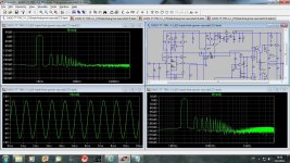
This is the trouble of relying on SPICE for THD results.
There is no way TMC can give less than 0.002% THD at 20KHz closed loop in any class B or AB amp in practice with a stable TMC loop about the output stage.
EC on the other hand can give less than 0.0006% at 20KHz closed loop with ease.
For the amp with BJT outputs there is no need for EC.
This is not true. A BJT output amp will benefit a substantial amout from EC, significantly more so than with TMC.
This is not true. A BJT output amp will benefit a substantial amout from EC, significantly more so than with TMC.
Can you prove that? Show some simulation. Do you need distortion lower then I showed in my post, and with simple TMC at that?
dado
beyond reproach
No need for Mike to prove and/or substantiate anything, as "his semiconductor physics background is beyond reproach" 🙄
Cheers,
E.
Can you prove that? Show some simulation. Do you need distortion lower then I showed in my post, and with simple TMC at that?
dado
No need for Mike to prove and/or substantiate anything, as "his semiconductor physics background is beyond reproach" 🙄
Cheers,
E.
Can you prove that? Show some simulation. Do you need distortion lower then I showed in my post, and with simple TMC at that?
dado
Distortion in SPICE is highly misleading, bordering on completely useless.
No need for Mike to prove and/or substantiate anything, as "his semiconductor physics background is beyond reproach" 🙄
Cheers,
E.
OK I accept that(without sarcasm), but still how is possible that spice simulation is good enough for EC and not for TMC.
You also use spice simulation to prove your point and what result you get fot EC is acceptable, but for TMC must be wrong??
I appreciate if someone can present real life TMC amp and how good it could be.
I made some TMC amps, but have no means to measure so low distortion.
Soundwise I liked what I've heard.
dado
....."his semiconductor physics background is beyond reproach" 🙄
Cheers,
E.
Thank you for making this wonderfully correct and astute observation...😛
- Home
- Amplifiers
- Solid State
- Bob Cordell Interview: Error Correction