....... how is possible that spice simulation is good enough for EC and not for TMC.
SPICE THD simulation is no good for anything, EC, TMC, TPC or anything else....
SPICE THD simulation is no good for anything, EC, TMC, TPC or anything else....
'unfriendly' models
Hi Dado,
These are very good questions. I've simmed a lot of amps and the THD figures were always in accordance (within say 10%) with real life specs.
So I also don't understand why simulating a HEC amp is okay and a sim of a TMC amp is doomed to fail.
Perhaps Mike is using HEC (and TPC!) 'friendly' models and TMC 'unfriendly' models. 😉
Cheers,
E.
OK I accept that(without sarcasm), but still how is possible that spice simulation is good enough for EC and not for TMC.
You also use spice simulation to prove your point and what result you get for EC is acceptable, but for TMC must be wrong??
I appreciate if someone can present real life TMC amp and how good it could be.
I made some TMC amps, but have no means to measure so low distortion.
Soundwise I liked what I've heard.
dado
Hi Dado,
These are very good questions. I've simmed a lot of amps and the THD figures were always in accordance (within say 10%) with real life specs.
So I also don't understand why simulating a HEC amp is okay and a sim of a TMC amp is doomed to fail.
Perhaps Mike is using HEC (and TPC!) 'friendly' models and TMC 'unfriendly' models. 😉
Cheers,
E.
So I also don't understand why simulating a HEC amp is okay and a sim of a TMC amp is doomed to fail.
At no point have I claimed the above.
To reiterate:
SPICE THD simulation is no good for anything, EC, TMC, TPC or anything else....
Hi Dado,
I've simmed a lot of amps and the THD figures were always in accordance (within say 10%) with real life specs.
To see how untrue this is, and how useless THD in SPICE is, run a simulation of Douglas Self's TMC amp in Jan Didden's Linear Audio Bookzine and compare the SPICE THD at 20Khz with Doug's measured results.
Insert a 80Khz filter at the output of the SPICE amp for fair comparison.
Last edited:
For the amp with BJT outputs there is no need for EC. A bit different TMC connection(reduced VAS loading) and distortion go down a little more. dado
Hi Dado,
Do I understand correctly that THD20 is only 0.72ppm? If so, then this is amazingly good for such a circuit, as it is far better than a standard blameless + TMC, which showed THD20 = 12ppm.
BTW, Douglas Self measured THD20+N = 15ppm (See Jan's 'bookzine' vol. 0, pp. 16-17)
In the meantime, I also simmed a blameless + HEC and got THD20 = 4ppm. Notice that this was achieved with an idealized HEC circuit, so real figures will be slightly higher. In the light of the latter figures, which I believe are fairly accurate, your THD20 is a major achievement. Could you explain in more detail which specific circuit details contributed to such extreme low distortion?
Cheers, E.
Last edited:
Hi Dado,
Do I understand correctly that THD20 is only 0.72ppm? If so, then this is amazingly good for such a circuit, as it is far better than a standard blameless + TMC, which showed THD20 = 12ppm.
BTW, Douglas Self measured THD20+N = 15ppm (See Jan's 'bookzine' vol. 0, pp. 16-17)
In the meantime, I also simmed a blameless + HEC and got THD20 = 4ppm. Notice that this was achieved with an idealized HEC circuit, so real figures will be slightly higher. In the light of the latter figures, which I believe are fairly accurate, your THD20 is a major achievement. Could you explain in more detail which specific circuit details contributed to such extreme low distortion?
Cheers, E.
Hi Edmond,
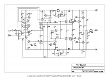
There nothing special in my circuit. I just tried to optimize each state separatelly.
Input state is NFET cascoded LTP with floated cascode.
VAS is buffered, and TMC is connected a bit differently, between LTP and cascode, not between cascode and current mirror. Output state is a Triple.
Loog gain(Negative Feedback) was set to 76dB from 0-10kHz. I did it to get better phase behavior not to lower TIM, I am not the one to believe that wide OLG is better. Not sure about spice models accuracy, I used some from Cordell and some from others from this forum.
If you like I can send you my LTspice files, just I need your email.
regards Dado
Attachments
Thanks Dado.
As for the spice files, please send them to me, together with all the models.
I will need them as I'm not sure if MicroCap (that's my sim vehicle) uses the same models from the standard library.
I'm curious to learn whether I will get the same THD figure (will do it after the weekend).
See your PM box for my email address.
Cheers,
E.
Hi all !!!
Good to see the embers glow again after all this years with just a hint of stirring !! [snip] Rodolfo
Rodolfo! Good to see you're still alive and kicking 😉
jan
SPICE THD simulation is no good for anything, EC, TMC, TPC or anything else....
Hi Mike,
I'm sorry but I cannot agree with your statement that SPICE THD simulation is no good for anything. It certainly has its limits, and is much more useful when good models are employed, but that is far from saying it is useless.
It is very good for quantitative comparisons for different topologies and for different sets of component values.
The fact that its THD simulations do not cover some non-idealities that are not modeled is no fault of SPICE.
If you feel this way about SPICE, perhaps you can give some concrete examples (best from your own experience) that we can discuss.
Cheers,
Bob
It is very good for quantitative comparisons for different topologies and for different sets of component values.
What I meant was it's useless when compared to real world measurements.
Conclusions about the ultimate performance of a circuit cannot be made from SPICE THD.
Hi Edmond,
There nothing special in my circuit. I just tried to optimize each state separatelly.
Input state is NFET cascoded LTP with floated cascode.
VAS is buffered, and TMC is connected a bit differently, between LTP and cascode, not between cascode and current mirror. Output state is a Triple.
Loog gain(Negative Feedback) was set to 76dB from 0-10kHz. I did it to get better phase behavior not to lower TIM, I am not the one to believe that wide OLG is better. Not sure about spice models accuracy, I used some from Cordell and some from others from this forum.
If you like I can send you my LTspice files, just I need your email.
regards Dado
Hello Dado
This may seem like a stupid request but can you clip the amp by driving input with sine wave into 2 and 4 ohm load and see what the overload recovery looks like and post results if possible.
Regards
Arthur
Hello Dado
This may seem like a stupid request but can you clip the amp by driving input with sine wave into 2 and 4 ohm load and see what the overload recovery looks like and post results if possible.
Regards
Arthur
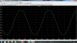
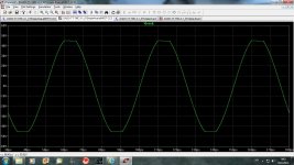
Hi Arthur,
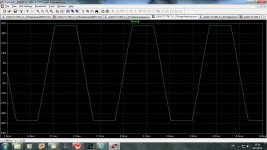
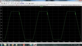
That was not a stupid request, not at all. I can see some small oscilatios when clipped on 2 ohm load.
in this order: 8ohm, 4ohm, last two 2ohm
regards
Dado
Attachments
Hello Dado
Thanks for posting the simulator results. Have you built the amp, if you have could you check what the amp does in real life into 2 ohms.
Is it possible for me too to get a copy of the Ltspice schematic with all the models of what you have used, I will simulate it in another simulator (simetrix). I haves sent you my email too.
Regards
Arthur
Hello Dado
Thanks for posting the simulator results. Have you built the amp, if you have could you check what the amp does in real life into 2 ohms.
Is it possible for me too to get a copy of the Ltspice schematic with all the models of what you have used, I will simulate it in another simulator (simetrix). I haves sent you my email too.
Regards
Arthur
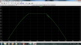
I have built the amp and connected to my lab power supply(+-30V, 2A) just to see if there some faults on the PCB. I have to build proper power supply firts(in next weeks) and than I will test it properly. I do not have proper 2ohm load(just 8ohm and 4ohm) specially not for clipping test.
regards
Dado
Dad,
is that a little bit of rail hanging on returning from clip @ +ve swing?
If it is then that seems to be what is promoting the sudden step input that gives the +ve return swing the kick into oscillation.
Maybe this is a sign that those anti-clip/saturation diodes might be useful.
is that a little bit of rail hanging on returning from clip @ +ve swing?
If it is then that seems to be what is promoting the sudden step input that gives the +ve return swing the kick into oscillation.
Maybe this is a sign that those anti-clip/saturation diodes might be useful.
another 8r0 dummy and you have both 16r and 2r0 dummies.I do not have proper 2ohm load(just 8ohm and 4ohm) specially not for clipping test.
Dad,
is that a little bit of rail hanging on returning from clip @ +ve swing?
If it is then that seems to be what is promoting the sudden step input that gives the +ve return swing the kick into oscillation.
Maybe this is a sign that those anti-clip/saturation diodes might be useful.another 8r0 dummy and you have both 16r and 2r0 dummies.
AndrewT,
Yes of course there is solution, separated power supply with higher voltage for input state then for output, and use of Backer clamps. I tried it in simulation and it works. To keep it simle for a moment I have one power supply and hope that the clipping will not be to bad, I have to test in real world first. The simulated clipping it tipical for VAS with TMC, not oscilation part of course.
For 2ohm dummy I have to buy a new set of resistors and aditional heathsink. Actually i have now two sets of 15//18omh 50W resistors on the same heathsink(not to big one) so I have 8ohm or when parallel 4ohm load.
Dado
Attachments
Clamp
Hello Dado
Is the amp you are simulating with a clamp into 2 ohms and 2 pairs of output or 1 pair of output devices.
What clamp are you using and where is it connected.
Regards
Arthur
Hello Dado
Is the amp you are simulating with a clamp into 2 ohms and 2 pairs of output or 1 pair of output devices.
What clamp are you using and where is it connected.
Regards
Arthur
Hello Dado
Is the amp you are simulating with a clamp into 2 ohms and 2 pairs of output or 1 pair of output devices.
What clamp are you using and where is it connected.
Regards
Arthur
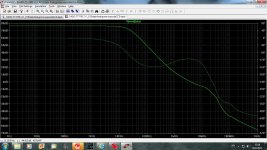
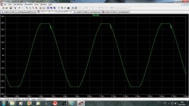
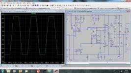
That was simulated into 6ohm 1kHz. Here is into 2ohm, first one at 20kHz(maybe that is to high frequence for clipping simulation??? the simulation already presented were at 20kHz too).
Firts diagram at 20kHz(oscilation present), and second one at 1kHz(no oscilation) and you can see clamping. Do you have suggestion to improve it?
dado
Attachments
What I meant was it's useless when compared to real world measurements.
Conclusions about the ultimate performance of a circuit cannot be made from SPICE THD.
Hi Mike,
I still don't agree with your statement above.
First of all, the statement is way too much of a generalization.
Secondly, you do not explain why you feel this way. Is your opinion based on simulation and building of an amplifier yourself? In other words, what have you personally done to arrive at this conclusion?
I'll assume that you did the simulation and compared it to an amplifier, and failed to achieve reasonable correlation. Can you fill us in on what you did? What the simulated distortion too high or too low?
Even so, it still seems inappropriate to make such a general statement. Just because you failed to get reasonable correlation does not mean that others did not. Maybe you just did not do a good job. How are we to know that?
Or do you base your assertion on what you have heard or your own version of theory. There is nothing wrong with making an assertion based on your own version of theory, but you need to, at minimum, back it up with explanation. This is what you have not done.
Cheers,
Bob
- Home
- Amplifiers
- Solid State
- Bob Cordell Interview: Error Correction