Jan,
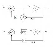
Consider the diagrams below. Fig 1 is Hawksford's EC and from this diagram I calculate the equations for Vn...
Vn = Vin + a.(Vn - Vout)
Vn.(1-a) = Vin - a.Vout
Vn = (Vin - a.Vout)/(1-a)
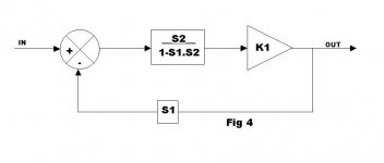
This last equation is shown in diagram form in Fig 3.
Fig 1 and Fig 3 are identical, mathmatically. From Fig 3 you can see the FB loop gain is = -a.N/(1-a).
In this arrangement, by our earlier definitions, the FB factor is a.
Brian
Consider the diagrams below. Fig 1 is Hawksford's EC and from this diagram I calculate the equations for Vn...
Vn = Vin + a.(Vn - Vout)
Vn.(1-a) = Vin - a.Vout
Vn = (Vin - a.Vout)/(1-a)
This last equation is shown in diagram form in Fig 3.
Fig 1 and Fig 3 are identical, mathmatically. From Fig 3 you can see the FB loop gain is = -a.N/(1-a).
In this arrangement, by our earlier definitions, the FB factor is a.
Brian
Attachments
janneman said:But we can leave that aside if you're not comfortable with it. There's a much easier way to confirm my results. As you know, the general formula for the cl gain for a feedback amp is Gcl=N/1-N.F, where N is the forward gain as we used, and F is what is sometimes called loop transmission, or loop gain or, as you prefer, FB loop gain.
We found earlier that the cl gain for Hec is Gcl=N/(1-a+aN), so the loop transmission or FB loop gain F of course is the exact same value of a(1-N) I gave in my earlier post.
Let me try this. In the conventional circuit with forward gain A and FB path gain B (aka FB factor), the overall gain G = A/(1+AB). The FB loop gain is -AB.
Ghec = N/(1-a+aN)
divide top and bottom by (1-a)...
Ghec = [N/(1-a)] / [1 + aN/(1-a)]
this is now in the form we want.
So A maps to N/(1-a) and B maps to a. Giving FB factor = a and FB loop gain = -a.N/(1-a)
Hi Jan,
With all respect, I also have some trouble with your transformation (post #3552 and pic below). Although mathematically correct in the sense that if S1=S2=1, the X-fer function becomes independent of K1 (i.e. no distortion), I'm afraid your model does not reflect the real HEC, as there are a few things that bother me:
1. The expression in the FB loop contains a dependent term 1/K1, because it's also present in the forward loop (as K1). I wonder if this is 'legal'. At least it blurs the analysis.
2. The original HEC circuit doesn't contain such 1/K1 gain block (let alone that we can build such thing in real life).
For these reasons I think that Brian's transformation is more appropriate.
Regards,
Edmond.
edit: Brian's FB loop gain = -a.N/(1-a) makes clear that if a=1 we get an infinite loop gain!
Attachments
Brian, Edmond, I appreciate and understand your concerns. And Brian, I see how you get to your transformation.
It's not that I try to persist against knowing better. But there's one major hangup I have. When I look at the original Hec circuit, I see that when N approaches 1, the actual feedback signal going into the inverting input of the input summer approaches zero. That means I can cut that signal and nothing happens, except for a slight change in Vout when N is not exactly 1.
Now, I've build several of these circuits. And ALL of them do exactly that: Use an EF for N with say olg of 0.95, cut the feedback signal into the input summer, and Vout sags just 5% or so.
Now if I look at Brian's circuit, if I cut the feedback loop, Vout goes through the roof. That is completely at variance with the physical circuit. An impossible situation!
Jan Didden
Hi jan & Brian,
This simply means that both transformations are not 100% valid. They only highlight some specific aspect, but not all of them.
Brian's model makes clear that there exists a loop with large gain and Jan's model shows correctly what happens if the FB signal to the input summer (S2) is disabled.
Regards,
Edmond.
janneman said:Now if I look at Brian's circuit, if I cut the feedback loop, Vout goes through the roof. That is completely at variance with the physical circuit. An impossible situation!
That's easy to explain. When you "cut" the NFB input to the Vin summer, it is mathematically equivalent to making a=0. In my equivalent circuit, if you set a=0 it will behave as a simple follower too. In a topologically equivalent, real implementation of my circuit, making a=0 might require more than cutting one connection though.
You can, however, observe exactly the same behaviour by cutting the global loop in the same place in either circuit. For instance, cut at the input to N or at the FB connection to Vout. Both real-life circuits will behave similarly (if their equations are the same) - probably oscillation or latch-up.
Edmond Stuart said:Hi Jan,
With all respect, I also have some trouble with your transformation (post #3552 and pic below). Although mathematically correct in the sense that if S1=S2=1, the X-fer function becomes independent of K1 (i.e. no distortion), I'm afraid your model does not reflect the real HEC, as there are a few things that bother me:
1. The expression in the FB loop contains a dependent term 1/K1, because it's also present in the forward loop (as K1). I wonder if this is 'legal'. At least it blurs the analysis.
2. The original HEC circuit doesn't contain such 1/K1 gain block (let alone that we can build such thing in real life).
For these reasons I think that Brian's transformation is more appropriate.
Regards,
Edmond.
edit: Brian's FB loop gain = -a.N/(1-a) makes clear that if a=1 we get an infinite loop gain!
I agree. Jan's FB loop gain and FB factor calculations are in error because of the 1/K1 term in the feedback path. Let me try working these out using the system gain equation method.
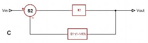
From Jan's diagram C:
gain Vo/Vin = S2.K1 / [ 1 + S1.S2.(K1 - 1) ]
or
Vo/Vin = S2.K1 / [ (1 - S1.S2) + S1.S2.K1 ]
divide top and bottom by (1 - S1.S2)...
Vo/Vin = [ S2.K1/(1-S1.S2) ] / [ 1 + S1.S2.K1/(1-S1.S2) ]
Mapping on to G = A/(1+AB) gives A = S2.K1/(1-S1.S2) and B = S1
So FB loop gain = -S1.S2.K1/(1-S1.S2) and FB factor = S1
Again, the FB loop gain is of the same form as -aN/(1-a) and the FB factor is independent of K1.
Fig C can be redrawn like this:
Attachments
traderbam said:[SNIP]
Ghec = N/(1-a+aN)
divide top and bottom by (1-a)...
Ghec = [N/(1-a)] / [1 + aN/(1-a)]
this is now in the form we want.
[snip]
Brian, I believe this operation is illegal at the point we're interested in (a=1) as we would divide by zero. Similarly in post above.
Looked at it in another way: You mapped the forward gain to N/(1-a). At the point where you say you have infinite fb, (a=1) you also have zero forward gain, so the infinite fb isn't really there.
Jan Didden
traderbam said:That's easy to explain. When you "cut" the NFB input to the Vin summer, it is mathematically equivalent to making a=0. In my equivalent circuit, if you set a=0 it will behave as a simple follower too. In a topologically equivalent, real implementation of my circuit, making a=0 might require more than cutting one connection though.[snip]
Yes and that is, IIRC also something I discussed some time ago with Edmond. By having 'a' in two places in the model means you have to treat them together so if you set a=0 in one place, you should also do it in the other place. Indeed, it seems the circuit becomes a follower.
If you cut the loop in this way (treat the two 'a'-s the same and making them = 0) you also have no longer the infinite fb.
Maybe that is the heart of the issue: I consider the circuit as a combination of feedback loops that are both there or both cut. That's why I cut at the input to the input summer. You seem to propose that we can cut either the pos fb loop, or only the neg feedback loop, and then look at the circuit attributes. Surely we get different results.
Jan Didden
Brian, Edmond,
I've just extensively edited my last few posts, sorry about that, but please check.
Jan Didden
I've just extensively edited my last few posts, sorry about that, but please check.
Jan Didden
I believe this is ok while we are still in algebraic manipulation mode and provided we do the same to the top and the bottom. Care must be taken, of course, when inserting numerical values into a final equation to avoid divide by zero or zero divided by zero issues.janneman said:Brian, I believe this operation is illegal at the point we're interested in (a=1) as we would divide by zero.
traderbam said:
I believe this is ok while we are still in algebraic manipulation mode and provided we do the same to the top and the bottom. Care must be taken, of course, when inserting numerical values into a final equation to avoid divide by zero or zero divided by zero issues.
Then you must remember that because of this manipulation, we can no longer draw any valid conclusions at a=1. So no conclusions that we have infinite fb or whatever loop gain at a=1.
This makes this particular manipulation less useful.
Jan Didden
I'm not following you. Cutting at the input to N or at the path from Vout are cutting the NFB loop only.janneman said:Maybe that is the heart of the issue: I consider the circuit as a combination of feedback loops that are both there or both cut. That's why I cut at the input to the input summer. You seem to propose that we can cut either the pos fb loop, or only the neg feedback loop, and then look at the circuit attributes. Surely we get different results.
traderbam said:
I'm not following you. Cutting at the input to N or at the path from Vout are cutting the NFB loop only.
Yes, that is correct. But *the* defining property of Hec is the carefully balanced combination of pos and neg feedback. If you want to open the fb loop in a Hec system, you must open both at the same time.
My view is that is you want to look at Hec loop gain or feedback gain you should cut the feedback loop between the output of the feedback element and the input to the input summer. Are you saying that this is the wrong way to do it?
Jan Didden
janneman said:Then you must remember that because of this manipulation, we can no longer draw any valid conclusions at a=1. So no conclusions that we have infinite fb or whatever loop gain at a=1.
This makes this particular manipulation less useful.
That is not correct. The magnitude of the FB loop gain is infinite for sure, but the phase changes during the transition through 1. Nothing to see here.
It might help a lot with your intuitive understanding to simulate the circuit.
Getting back to the original question, do you now think that the FB factor varies with the plant transfer function? NFB on demand?
traderbam said:
That is not correct. The magnitude of the FB loop gain is infinite for sure, but the phase changes during the transition through 1. Nothing to see here.
It might help a lot with your intuitive understanding to simulate the circuit.
Getting back to the original question, do you now think that the FB factor varies with the plant transfer function? NFB on demand?
Ohh, I've simmed it. And build it, as noted. Multiple times.
As noted, if you open the loop in your model by setting a=0, you must also set a=0 in the transformed block ahead of N. You can't take a parameter 'a' in a circuit, transform the circuit so that 'a' appears in two places, and then treat them as two independent parameters. I would hope we could agree on that one.
Setting *both* a=0 this way, (which is conceptually equivalent to my opening of the loop at the input of the input summer) shows no trace of any infinite fb.
And I must insist that your manipulation of that G/1-G.B by dividing by 1-a is not legal at a=1, although that is precisely the point where you say that the feedback becomes infinite. So this manipulation doesn't bring us forward, rather the opposite.
So far I think I still believe that the 'on demand feedback' term is appropriate. The *fraction* of Vout that is returned to the input varies with the plant gain. I also don't understand why the mere fact that there is a term 1/K1 in the fb loop in my model would make it invalid, unless I misunderstood your meaning here?
Edit: I do of course agree that if you open only the neg fb loop, you find infinite fb. But my point is that this is not telling you anything about the behaviour of the Hec circuit, the essence of which is the combined pos and neg fb.
Jan Didden
janneman said:Yes, that is correct. But *the* defining property of Hec is the carefully balanced combination of pos and neg feedback. If you want to open the fb loop in a Hec system, you must open both at the same time.
Yes, I have heard you describe this "balancing" as being a property of HEC before. But I don't yet see this myself. I would like to understand what you mean. Can you express this idea in a mathematical way?
The way I currently interpret the thing is that the PFB loop is nested within the NFB control loop. I can justify this by redrawing the HEC with the two loops shown separately and nested without changing the functionality of the system. The HEC is usually drawn with both loops sharing a common leg and this disguises the nesting.
My view is that is you want to look at Hec loop gain or feedback gain you should cut the feedback loop between the output of the feedback element and the input to the input summer. Are you saying that this is the wrong way to do it?
I am suggesting that is the wrong way to do it. The way to do it, as with any nested system, is to cut the single loop that senses the output. When you cut the input summer connection you are cutting both the control loop and the nested PFB loop at the same time. This is sort of like cutting the NFB path and the VAS miller loop at the same time.
If you are unsure about the maths behind the single-loop version of HEC that I posted, then perhaps you might care to simulate it.Originally posted by janneman Ohh, I've simmed it. And build it, as noted. Multiple times.
As noted, if you open the loop in your model by setting a=0, you must also set a=0 in the transformed block ahead of N. You can't take a parameter 'a' in a circuit, transform the circuit so that 'a' appears in two places, and then treat them as two independent parameters. I would hope we could agree on that one.
Setting *both* a=0 this way, (which is conceptually equivalent to my opening of the loop at the input of the input summer) shows no trace of any infinite fb.
I agree. When all a=0 there is no infinite FB in either circuit. Both circuits become simple followers. So?
And I must insist that your manipulation of that G/1-G.B by dividing by 1-a is not legal at a=1, although that is precisely the point where you say that the feedback becomes infinite. So this manipulation doesn't bring us forward, rather the opposite.
It is your right to insist. it would be more helpful to me if you could persuade with reasoning. You'll understand it better if you simulate it.
So far I think I still believe that the 'on demand feedback' term is appropriate. The *fraction* of Vout that is returned to the input varies with the plant gain. I also don't understand why the mere fact that there is a term 1/K1 in the fb loop in my model would make it invalid, unless I misunderstood your meaning here?
You mis-understand me. Your models A, B and C are fine. It is just that you cannot use C to calculate the FB loop gain directly because of the 1/K1 term. Edmond pointed this out earlier.
Edit: I do of course agree that if you open only the neg fb loop, you find infinite fb. But my point is that this is not telling you anything about the behaviour of the Hec circuit, the essence of which is the combined pos and neg fb.
Like I say, I do not comprehend this "essence" of which you speak. I would appreciate it if you, or anyone else, would try to explain it to me in a mathematical way. I don't yet see it in the system equations.
What seems sort of original to me about some HEC implementations is simply the use of a nested, tunable PFB loop as a nifty way to create an integrator with bags of gain at dc. Of course, gain at dc is almost never in short supply so I think this is of limited value. Other than that, it's just a servo circuit. A servo without PFB loop is just as easy to design. It also has the property that if you cut the NFB path, the circuit behaves as a follower.
Brian
edit
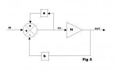
Here's a diagram of HEC showing the nesting and splitting the PFB loop scalar, a, from the NFB loop scalar, b.
Vout/Vin = N / (1-a+bN)
FB loop gain = -bN/(1-a)
FB factor = b
You can see that the infinite gain is determined by a alone. The NFB loop has no part in it. I see no special interaction between the loops; the loops are independent.
Attachments
correction
Jan,
I need to correct an error in my post 3568.
The method of fitting the system gain equation into form G=A/(1+AB) reveals the feedback factor B (as we are defining it) but the formula you proposed in post 3560 for calculating the FB loop gain as -AB is not generally correct. It worked for the HEC circuit and this gave me confidence to try it on your fig C...but it does not work in this case.
So in your fig C., the FB factor (defining it as B above) is S1 as stated. But the FB loop gain is = -S1.S2.(K1-1); the product of the gain elements in the loop. Which is how I normally calculate it.
Note: the FB loop gain for HEC is correct as previously stated: -aN/(1-a) and the FB factor is a.
Brian
PS: I think we need to define, mathematically, your hypothesis of "NFB on demand". Unless it is defined this way, its existence cannot be verified.
- Home
- Amplifiers
- Solid State
- Bob Cordell Interview: Error Correction