Edmond Stuart said:... But can it compete (spec-wise and $-wise) with a top end analog design (THD20<1ppm)?.....
Left to speculate, admittedly, I cannot help looking at the increasingly massive, indexpensive digital muscle working everywhere as a strong message in the wall.
Were I told only 10 years back I could have a color multimedia real time digital communication terminal in the Mb/s range, battery operated and costing below U$ 100 I should have laughed in contempt. So much for experienced wisdom.
Again, I mostly think this approach (EC) may hold promise in a purely digital environment, including the power output. In fact the "Error Correction" label may be dropped entirely, what matters is the concept, not an invocation to particular instances of application.
And no matter whether the mass market cares or not about sub ppm distortion, if it can be done inexpensively, then there is no reason to do otherwise no matter who ends up using it.
Rodolfo
for a way to look at "distortion flow" in a feedback circuit:
Cherry’s “ESTIMATES OF NONLINEAR DISTORTION IN FEEDBACK AMPLIFIERS” JAES V48#4 2000 p299-313 provides a method of calculating individual component distortion mechanisms contribution to overall distortion of a amplifier, more importantly it gives a intellectual framework for reasoning about distortion and feedback in a feedback amplifier. The example calculations for a simple audio amplifier circuit in the article also would give you some perspective that will make much of this wandering about in simulation land more directed and informative.
Cherry’s “ESTIMATES OF NONLINEAR DISTORTION IN FEEDBACK AMPLIFIERS” JAES V48#4 2000 p299-313 provides a method of calculating individual component distortion mechanisms contribution to overall distortion of a amplifier, more importantly it gives a intellectual framework for reasoning about distortion and feedback in a feedback amplifier. The example calculations for a simple audio amplifier circuit in the article also would give you some perspective that will make much of this wandering about in simulation land more directed and informative.
I will look into that paper, I think I know where to get it.
Thanks for the pointer.
Jan didden
Thanks for the pointer.
Jan didden
ingrast said:.........
Again, I mostly think this approach (EC) may hold promise in a purely digital environment, including the power output.
..........
Rodolfo
True, in the digital domain the sky is the limit. However, I think that two things will never go digital: the begin and end of the audio chain (i.e. transducers).
Cheers,
Edmond.
Peace
Hi Bob,
Well, maybe legitimate, but equally useful? I have my doubts. Does view nr. 2 and 3 give any clou about stability issues and the need for frequency compensation?
Semantics? Yes! In particular WRT nr. 3. This view might suggest that the NFB-factor is 'on demand' (i.e. variable), which is certainly not the case. Only the amplitude is 'on demand'.
Agreed.
I'm such a guy as well.
Why didn't Bell Labs invent TMC as well.🙂
The funny thing is that I designed the NFB-OPS just to show that it is (almost) equivalent to HEC-OPS (in terms of distortion, phase shift, stability and degrees of freedom). So it was born not by attacking the problem, rather by attacking the other views.
Cheers, and peace of course,
Edmond.
Bob Cordell said:Hi Edmond,
Peace.
The three ways of looking at EC,
1) conventional NFB with very large loop gain from inner PFB loop,
2) error correction as Hawksford described it,
3) NFB on demand,
are useful ways of looking at the beast to different people in different circumstances. Analyzed properly, all three will give the same right answer.
Hi Bob,
Well, maybe legitimate, but equally useful? I have my doubts. Does view nr. 2 and 3 give any clou about stability issues and the need for frequency compensation?
Some will find views 2 and 3 worthless, and they are welcome to stick soley with view #1. Some will view view #2 as a fraudulent description for employing the term "error correction". So be it. Just semantics. I get offended by other's choices of semantics in certain situations as well.
Semantics? Yes! In particular WRT nr. 3. This view might suggest that the NFB-factor is 'on demand' (i.e. variable), which is certainly not the case. Only the amplitude is 'on demand'.
Back at Bell Labs in the '70s, some of us linear IC designers argued about whether the function of a transistor in a circuit should be viewed as one of current gain or as one of transconductance. Obviously, both views are equally correct when applied properly.
Agreed.
Some designers were more comfortable with the Beta view, while others were more comfortable with the transconductance view. I'm a transconductance kind of guy.
I'm such a guy as well.
BTW, TPC was employed by Bell Labs in operational amplifiers since the early '70's, where it was called T compensation. These op amps were used in high-performance active filters where the extra in-band open-loop gain was important (especially with early-generation op amps with limited GBW).
Why didn't Bell Labs invent TMC as well.🙂
I think that you have shown that alternative approaches to distortion reduction that are more like conventional NFB, like high levels of tight local output stage NFB and TMC, can be just as effective as HEC. That is a good thing. The more ways we have of attacking the problem, the better.
Peace,
Bob
The funny thing is that I designed the NFB-OPS just to show that it is (almost) equivalent to HEC-OPS (in terms of distortion, phase shift, stability and degrees of freedom). So it was born not by attacking the problem, rather by attacking the other views.
Cheers, and peace of course,
Edmond.
Hi Edmond,
If you calculate the feedback factor of a Hec loop, with the forward gain=A and the feedback summer gain=B (the summer that sums the feedback from A's output and input),
you get B(1-1/A). Isn't that *factor* dependent on A?
Jan Didden
If you calculate the feedback factor of a Hec loop, with the forward gain=A and the feedback summer gain=B (the summer that sums the feedback from A's output and input),
you get B(1-1/A). Isn't that *factor* dependent on A?
Jan Didden
Edmond Stuart said:
True, in the digital domain the sky is the limit. However, I think that two things will never go digital: the begin and end of the audio chain (i.e. transducers).
Cheers,
Edmond.
While there is no alternative in sight, I should not bet my life on that, if history is some guide.
Rodolfo
janneman said:Hi Edmond,
If you calculate the feedback factor of a Hec loop, with the forward gain=A and the feedback summer gain=B (the summer that sums the feedback from A's output and input),
you get B(1-1/A). Isn't that *factor* dependent on A?
Jan Didden
Hi Jan,
You are right, that expression IS dependent on A.
When I was writing my previous post, I already knew that something was not entirely correct and needs further explanation. What I was trying to say is that NFB loop gain as defined by view #1 (instead of NFB factor), is quite high, no matter if A=0.98 or 0.95 or whatever.
The 'on demand view' however, suggest that if A=1, then there is nothing to correct and consequently no feedback, because there is no feedback signal. BUT the loop gain (according to view #1) is still there!
Regards,
Edmond.
Hi Edmond,
See, that's something that has bothered me also for some time.
In the case that A=1, as you say, the fb factor is zero. BUT, you state, according to view # 1 the (high) nfb is still there.
I don't understand that. Even if you consider view #1 a better view, it doesn't make the circuit a high fb circuit. The circuit is what it is. In the current case, A=1, I can replace the connection between the fb summer and the input summer with a broomstick, and nothing changes. I can throw out everything related to the feedback stuff, and nothing changes. How can the high feedback be there if it has no effect at all whether it is there or not?
Jan Didden
I also agree with Edmond. Fab. 😎
A new year and fresh enthusiasm to explain the dilemma you are having, Jan. I am used to using mathematical equations to explain things so I may not be effective in other ways. But let me try.
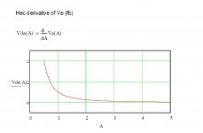
I think the basic mistake you are making is to confuse the absolute difference between two things and the slope of the difference. Yes, in an idealized HEC circuit, when the input Vi is equal to the output Vo then the NFB signal Ve is zero. BUT, this is not equivalent to saying there is no NFB.
Why? Because the NFB "force", if you will, is related to the slope of the graph of Ve plotted against (Vo - Vi). It is the slope of the curve that determines the "amount" of feedback, not the absolute value of Ve.
Does that make any sense?
Originally posted by janneman
Hi Edmond,
See, that's something that has bothered me also for some time.
In the case that A=1, as you say, the fb factor is zero. BUT, you state, according to view # 1 the (high) nfb is still there.
I don't understand that. Even if you consider view #1 a better view, it doesn't make the circuit a high fb circuit. The circuit is what it is. In the current case, A=1, I can replace the connection between the fb summer and the input summer with a broomstick, and nothing changes. I can throw out everything related to the feedback stuff, and nothing changes. How can the high feedback be there if it has no effect at all whether it is there or not?
A new year and fresh enthusiasm to explain the dilemma you are having, Jan. I am used to using mathematical equations to explain things so I may not be effective in other ways. But let me try.
I think the basic mistake you are making is to confuse the absolute difference between two things and the slope of the difference. Yes, in an idealized HEC circuit, when the input Vi is equal to the output Vo then the NFB signal Ve is zero. BUT, this is not equivalent to saying there is no NFB.
Why? Because the NFB "force", if you will, is related to the slope of the graph of Ve plotted against (Vo - Vi). It is the slope of the curve that determines the "amount" of feedback, not the absolute value of Ve.
Does that make any sense?
traderbam said:I also agree with Edmond. Fab. 😎
A new year and fresh enthusiasm to explain the dilemma you are having, Jan. I am used to using mathematical equations to explain things so I may not be effective in other ways. But let me try.
I think the basic mistake you are making is to confuse the absolute difference between two things and the slope of the difference. Yes, in an idealized HEC circuit, when the input Vi is equal to the output Vo then the NFB signal Ve is zero. BUT, this is not equivalent to saying there is no NFB.
Why? Because the NFB "force", if you will, is related to the slope of the graph of Ve plotted against (Vo - Vi). It is the slope of the curve that determines the "amount" of feedback, not the absolute value of Ve.
Does that make any sense?
Let me try. If we slightly deviate from the condition A=1, we see that both the feedback 'amount' as well as the feedback factor start to increase from zero to some small value.
What is happening to the Ve slope in this regime?
Edit: Is your Ve the input to the forward block A or the output of the feedback summer?
Jan Didden
Re: Peace
Hi Edmond,
Glad to see you are as feisty as ever.
Bell Labs did not invent TMC because they did not have the necessity to invent it 🙂. Just joking. They had a lot of smart people there, but they did not invent everything.
To answer your question with tongue only partially in cheek: 1) they did not make audio power amplifiers; 2) They had full-complementary BJTs in their op amps, so the output stage was not as big a problem as it might have been, especially in line-level circuits.
Cheers,
Bob
Edmond Stuart said:
Hi Bob,
Well, maybe legitimate, but equally useful? I have my doubts. Does view nr. 2 and 3 give any clou about stability issues and the need for frequency compensation?
Semantics? Yes! In particular WRT nr. 3. This view might suggest that the NFB-factor is 'on demand' (i.e. variable), which is certainly not the case. Only the amplitude is 'on demand'.
Agreed.
I'm such a guy as well.
Why didn't Bell Labs invent TMC as well.🙂
The funny thing is that I designed the NFB-OPS just to show that it is (almost) equivalent to HEC-OPS (in terms of distortion, phase shift, stability and degrees of freedom). So it was born not by attacking the problem, rather by attacking the other views.
Cheers, and peace of course,
Edmond.
Hi Edmond,
Glad to see you are as feisty as ever.
Bell Labs did not invent TMC because they did not have the necessity to invent it 🙂. Just joking. They had a lot of smart people there, but they did not invent everything.
To answer your question with tongue only partially in cheek: 1) they did not make audio power amplifiers; 2) They had full-complementary BJTs in their op amps, so the output stage was not as big a problem as it might have been, especially in line-level circuits.
Cheers,
Bob
confusing symantics?
Hi Jan & Brian,
I think the confusion or disagreement stems from using different definitions of NFB factor, NFB loop gain, effective feedback etc. It all depends on where the loop is broken. If we look again at: http://www.diyaudio.com/forums/showthread.php?postid=1282575#post1282575 , fig. 2 and 3, we get totally different figures: -33.98dB and 99.82dB respectively. Is this the source of confusion?
Regards,
Edmond.
janneman said:
Let me try. If we slightly deviate from the condition A=1, we see that both the feedback 'amount' as well as the feedback factor start to increase from zero to some small value.
What is happening to the Ve slope in this regime?
Edit: Is your Ve the input to the forward block A or the output of the feedback summer?
Jan Didden
We made need to agree on language. I consider feedback factor and feedback loop gain and feedback amount to be the same thing.
Suppose you are riding a bicycle. There is a narrow, perfectly straight line drawn along the road before you. Your task is to keep your front wheel centred on the line. The steering force your hands apply to the handbars is your NFB signal.
In the idealized HEC with A=1, is like saying the bicycle follows the line exactly and so you don't need to apply any force with your hands. Even if you take your hands off the handlebars nothing changes.
When the bicycle is allowed to deviate from the line, the steering force you apply is related to the size of the deviation that you measure with your eyes. If you drew a graph of steering force vs deviation, the slope of that line would be proportional to the feedback factor.
In the idealized HEC diagram, the feedback factor is infinite. So a deviation is not possible because an infinite steering force will stop it.
A conceptual mistake is to mix up the condition where you can take your hands off the handlebars with there being no NFB at play. The feedback factor is defined as the response to a deviation. So you can not quantify the feedback factor if you assume there is no possibility of deviation. Nevertheless, the NFB is always functioning and it is the nature of its response to deviation that is important in defining the characteristics of the system.
traderbam said:I also agree with Edmond. Fab. 😎
A new year and fresh enthusiasm to explain the dilemma you are having, Jan. I am used to using mathematical equations to explain things so I may not be effective in other ways. But let me try.
I think the basic mistake you are making is to confuse the absolute difference between two things and the slope of the difference. Yes, in an idealized HEC circuit, when the input Vi is equal to the output Vo then the NFB signal Ve is zero. BUT, this is not equivalent to saying there is no NFB.
Why? Because the NFB "force", if you will, is related to the slope of the graph of Ve plotted against (Vo - Vi). It is the slope of the curve that determines the "amount" of feedback, not the absolute value of Ve.
Does that make any sense?
OK Brian, thanks for your pointer, here's what I have found.
We seem to have established that both the fb value and factor go through zero at A=1 and then incrementally grow with A deviating from 1. That lends credibility to the 'feedback on demand' view.
Your and Edmonds position is - in order to reconcile view #1 and view #3 - that even if the fb value and factor is zero, the fb 'power' is still there, and you referred to the Ve slope. (Ve being the output from the fb summer going to the input summer, I assumed).
I asked MathCad to plot the Ve curve. As expected, Ve=0 for A=1. At that point (A=1), the slope of Ve=1. That means that very close to A=1, Ve and A change at the same ratio, correct? So, that did give me some additional insight of what's going on near A=1.
Unfortunately, I still don't understand what it means that 'the power' of the fb is still there even when you can cut the input to the input summer or delete all traces of fb (both pos and neg) without any change. What is the physical effect of the slope being 1, other than showing how Ve changes wrt A around A=1? Or should I just stop worrying and see it as a mathematical thing that provides the connection between view #1 and #3, with no real physical complement?
Edit: we xposted...
Edit-2: Just read you last post. Makes it a lot clearer. Let me digest it...
Jan Didden
Attachments
Re: Re: Peace
Thx. 🙂
Okay, not everything, but they did the most important invention of 20th century!
I think you are quite right, as they didn't play with high power (MOSFET) audio amps. So they didn't need TMC at all (which only reduces the distortion of the output stage).
Cheers,
Edmond.
Bob Cordell said:Hi Edmond,
Glad to see you are as feisty as ever.
Thx. 🙂
Bell Labs did not invent TMC because they did not have the necessity to invent it 🙂. Just joking. They had a lot of smart people there, but they did not invent everything.
Okay, not everything, but they did the most important invention of 20th century!
To answer your question with tongue only partially in cheek: 1) they did not make audio power amplifiers; 2) They had full-complementary BJTs in their op amps, so the output stage was not as big a problem as it might have been, especially in line-level circuits.
Cheers,
Bob
I think you are quite right, as they didn't play with high power (MOSFET) audio amps. So they didn't need TMC at all (which only reduces the distortion of the output stage).
Cheers,
Edmond.
traderbam said:
We made need to agree on language. I consider feedback factor and feedback loop gain and feedback amount to be the same thing.
Suppose you are riding a bicycle. There is a narrow, perfectly straight line drawn along the road before you. Your task is to keep your front wheel centred on the line. The steering force your hands apply to the handbars is your NFB signal.
In the idealized HEC with A=1, is like saying the bicycle follows the line exactly and so you don't need to apply any force with your hands. Even if you take your hands off the handlebars nothing changes.
When the bicycle is allowed to deviate from the line, the steering force you apply is related to the size of the deviation that you measure with your eyes. If you drew a graph of steering force vs deviation, the slope of that line would be proportional to the feedback factor.
In the idealized HEC diagram, the feedback factor is infinite. So a deviation is not possible because an infinite steering force will stop it.
A conceptual mistake is to mix up the condition where you can take your hands off the handlebars with there being no NFB at play. The feedback factor is defined as the response to a deviation. So you can not quantify the feedback factor if you assume there is no possibility of deviation. Nevertheless, the NFB is always functioning and it is the nature of its response to deviation that is important in defining the characteristics of the system.
OK, I think I understand better your reasoning. Even if at the time where there is no deviation, and I take my hands of the handlebars, still, when there *would* be a deviation, I'll react to it. So, the fb, as a system attribute, is still there even if latent. Not sure where this leads, but I get your reasoning.
I've done some more thinking about that Ve derivative. I would have thought that at a point where the fb would be infinite, the derivative of the feedback (factor) would be 0. Indeed, if you plot Ve for a range of A (see attachment) you find that at much higher A, the derivative asymptotes to 0. And, as noted, for A=1, the derivative = 1 as well.
Now if A becomes much higher that 1, we can expect the 'effective' fb to grow much higher as the nfb part of the combined loop starts to increase and dominate. That would jive with the derivative going to 0. But that would also indicate that the total system feedback at A=1 isn't infinite. Since the total system feedback is build up from a negative feedback part and a positive feedback part (giving an infinite gain block), those parts being exactly equal at A=1, this all seems to make sense.
If I have some time I'll try to do the same calculation and plots for a nfb-only system with an infinite forward gain. See how that looks.
Thanks for bearing with me Brian, I'm really getting a lot out of this.
Jan Didden
Attachments
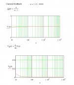
I did the same curves for a high-fb amp, with a forward gain=a and unity feedback. See attached.
It seems that when a (the OL gain) gets above 100 we are already very close to the situation for a>infinity. The 'Va' (Ve in the other case) gets close to 1, and the derivative gets close to 0.
This appears to be consistent with the Hec situation.
Jan Didden
It seems that when a (the OL gain) gets above 100 we are already very close to the situation for a>infinity. The 'Va' (Ve in the other case) gets close to 1, and the derivative gets close to 0.
This appears to be consistent with the Hec situation.
Jan Didden
Attachments
Re: confusing symantics?
Hi Edmond,
Possibly there is some miscommunication there. I also have this 'deja vu' feeling...
Anyway. The system response is determined by the combination of pos and neg feedback. This feedback is summed and send to the inverting input of the input summer. It seems to me logical that when you want to inspect the loop by breaking it, you would break it between the output of the feedback summer and the input of the input summer, because then you really break the (combined) feedback loop.
You can also redraw this circuit with a unity gain positive feedback loop in the forward path (giving rise to infinite forward gain), and a neg feedback loop from output to the inverting input. In this situation, the two circuits have identical transfer curves. Now, if you would want to inspect *this* loop by breaking it, it gets complicated. If you would just break the global nfb loop, you have no longer the same situation as when you broke the loop in the original circuit, because you only broke part of the fb loop (leaving the pos loop intact). Of course you measure different values in this situation. If you only break the nfb loop, you are no longer looking at the original circuit but at a completely different one. So this doesn't tell you anything about the original Hec circuit.
Jan Didden
Edmond Stuart said:Hi Jan & Brian,
I think the confusion or disagreement stems from using different definitions of NFB factor, NFB loop gain, effective feedback etc. It all depends on where the loop is broken. If we look again at: http://www.diyaudio.com/forums/showthread.php?postid=1282575#post1282575 , fig. 2 and 3, we get totally different figures: -33.98dB and 99.82dB respectively. Is this the source of confusion?
Regards,
Edmond.
Hi Edmond,
Possibly there is some miscommunication there. I also have this 'deja vu' feeling...
Anyway. The system response is determined by the combination of pos and neg feedback. This feedback is summed and send to the inverting input of the input summer. It seems to me logical that when you want to inspect the loop by breaking it, you would break it between the output of the feedback summer and the input of the input summer, because then you really break the (combined) feedback loop.
You can also redraw this circuit with a unity gain positive feedback loop in the forward path (giving rise to infinite forward gain), and a neg feedback loop from output to the inverting input. In this situation, the two circuits have identical transfer curves. Now, if you would want to inspect *this* loop by breaking it, it gets complicated. If you would just break the global nfb loop, you have no longer the same situation as when you broke the loop in the original circuit, because you only broke part of the fb loop (leaving the pos loop intact). Of course you measure different values in this situation. If you only break the nfb loop, you are no longer looking at the original circuit but at a completely different one. So this doesn't tell you anything about the original Hec circuit.
Jan Didden
- Home
- Amplifiers
- Solid State
- Bob Cordell Interview: Error Correction