ODNF
Hi David,
Thanks for the reference. But are you sure this patent describes the basics of the Luxman B1000? The point is that the amp in this patent does use global NFB and it does use several "phase compensation" caps (3 times) in the "music signal path". All in all rather confusing.
BTW, the ODNF circuit seems indeed to be a variant on EC, although, according to a quick sim, of questionable value.
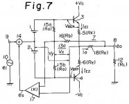
In Fig.2, the balance equation is: R21||R22=R43+R44.
Cheers,
Edmond.
lumanauw said:Luxman ODNF use a 2nd differential system to compare input and output, and put it as a signal for halfside of VAS.
It resembles fig.2 in this patent 4785257
Hi David,
Thanks for the reference. But are you sure this patent describes the basics of the Luxman B1000? The point is that the amp in this patent does use global NFB and it does use several "phase compensation" caps (3 times) in the "music signal path". All in all rather confusing.
BTW, the ODNF circuit seems indeed to be a variant on EC, although, according to a quick sim, of questionable value.
In Fig.2, the balance equation is: R21||R22=R43+R44.
Cheers,
Edmond.
janneman said:[snip]
So, what you see, and for me was counterintuitive, that even with a K=0.9, the pos feedback is less than a dB.
Jan Didden
Hi Jan,
So, what are your conclusion?
Cheers,
Edmond.
Hi, Edmond,
I think it's not the Luxman patent.
I google "nippon gakki seizo kabushiki kaisha"/assignee of the patent, it is Yamaha, not Luxman.
Do you know which patent is used in that Luxman amp?
I think it's not the Luxman patent.
I google "nippon gakki seizo kabushiki kaisha"/assignee of the patent, it is Yamaha, not Luxman.
Do you know which patent is used in that Luxman amp?
lumanauw said:Hi, Edmond,
I think it's not the Luxman patent.
I google "nippon gakki seizo kabushiki kaisha"/assignee of the patent, it is Yamaha, not Luxman.
Do you know which patent is used in that Luxman amp?
Sorry, I don't know.
Cheers,
Edmond.
patent 4785257
Hi David,
In the mean time I had a closer look at this patent and discovered that it only works if the two 2kOhm resistors between input and output of the OPS are the only parts that load the VAS ouput. This means that you need a VAS with a very high output impedance. OK, that can be done with a Hawksford cascode. BUT..... you also need some kind of Miller compensation (absent in the patent!), which lowers the VAS output impedance considerable. Under these conditions, the EC circuit is totally ineffective and without Miller compensation, this amp is highly unstable.
I leave the conclusions to you.
Cheers,
Edmond.
lumanauw said:Luxman ODNF use a 2nd differential system to compare input and output, and put it as a signal for halfside of VAS.
It resembles fig.2 in this patent 4785257
Hi David,
In the mean time I had a closer look at this patent and discovered that it only works if the two 2kOhm resistors between input and output of the OPS are the only parts that load the VAS ouput. This means that you need a VAS with a very high output impedance. OK, that can be done with a Hawksford cascode. BUT..... you also need some kind of Miller compensation (absent in the patent!), which lowers the VAS output impedance considerable. Under these conditions, the EC circuit is totally ineffective and without Miller compensation, this amp is highly unstable.
I leave the conclusions to you.
Cheers,
Edmond.
Hi, Edmond,
Yes, I believe the impedance balance between those 2 points in EC is critical. It's the substantial part of EC, otherwise it will be called NFB.
Sometime ago, I built an EC system. It oscillates. I put compensation, it become stable, but you can guess, it lose it's function for fixing HF region. My initial goal when make this EC is exactly to help fixing HF response.
It's tricky to work with EC 😀
Re: ODNF @ Evolve
Hi Steven,
Care to translate the Japanese text, please (or give a clue)?
Cheers,
Edmond.
Steven said:
Hi Steven,
Care to translate the Japanese text, please (or give a clue)?
Cheers,
Edmond.
ODNF in plain old English...
Try this:
http://translate.google.com/transla...o/amp/odnf/odnf.htm&hl=en&ie=UTF8&sl=ja&tl=en
Cheers, Steven
Try this:
http://translate.google.com/transla...o/amp/odnf/odnf.htm&hl=en&ie=UTF8&sl=ja&tl=en
Cheers, Steven
Re: ODNF in plain old English...
Thanks Steven.
BTW, is this what you mean by "plain old English":
Negation strain in the best state vice-amp current drain is minimized signal components should be measured in this circuit, so print money... ?
Must be very "old" English 🙂
Anyhow, do you really think this link has something to do with the Luxman version of ODNF. As far as I can see, it uses a local NFB loop from the output and a traditional global NFB loop (see the last schematic).
Cheers,
Edmond.
Steven said:Try this:
http://translate.google.com/transla...o/amp/odnf/odnf.htm&hl=en&ie=UTF8&sl=ja&tl=en
Cheers, Steven
Thanks Steven.
BTW, is this what you mean by "plain old English":
Negation strain in the best state vice-amp current drain is minimized signal components should be measured in this circuit, so print money... ?
Must be very "old" English 🙂
Anyhow, do you really think this link has something to do with the Luxman version of ODNF. As far as I can see, it uses a local NFB loop from the output and a traditional global NFB loop (see the last schematic).
Cheers,
Edmond.
snoopy said:Hello
I'm not sure if this has been covered but Patent # 4476442 describes an error correction output stage that uses complimentary differential pairs. I believe this configuration was commercially used in the Yamaha M70 power amplifier.
Yep, inasmuch as 'K' in the figure is supposed to be '1' (and it is), this appears to be yet another Hawksford ec implementation. What is interesting is the timing: the patent was granted in 1984, Hawksford wrote his paper in 1981.
The earliest article about this configuration I found was from 1973 though.
L'histoire se répète...
Jan Didden
janneman said:
Yep, inasmuch as 'K' in the figure is supposed to be '1' (and it is), this appears to be yet another Hawksford ec implementation. What is interesting is the timing: the patent was granted in 1984, Hawksford wrote his paper in 1981.
The earliest article about this configuration I found was from 1973 though.
L'histoire se répète...
Jan Didden
To elaborate here is the guts of it from the patent. Although it does error correction it obviously was granted the patent because it achieves it in a different way to the Hawksford circuit.
snoopy said:
To elaborate here is the guts of it from the patent. Although it does error correction it obviously was granted the patent because it achieves it in a different way to the Hawksford circuit.
Well, I'm not a patent lawyer, but for me the concept is the same. The implementation is different then some of Hawksford's circuits, but I doubt that that patent holds up in court. I wouldn't bet on it.
Jan Didden
janneman said:
Well, I'm not a patent lawyer, but for me the concept is the same. The implementation is different then some of Hawksford's circuits, but I doubt that that patent holds up in court. I wouldn't bet on it.
Jan Didden
I was told by a patent lawyer once that an invention doesn't have to be something new. It can be based on a new way of implementing an existing invention or simply an improvement on an existing invention. In this case the way this patent does error correction is different to the Hawksford circuit but the results are similar so the patent would hold up in court. Something like that anyway. I'm not a patent lawyer either so someone else might like to clarify 😉
snoopy said:
I was told by a patent lawyer once that an invention doesn't have to be something new. It can be based on a new way of implementing an existing invention or simply an improvement on an existing invention. In this case the way this patent does error correction is different to the Hawksford circuit but the results are similar so the patent would hold up in court. Something like that anyway. I'm not a patent lawyer either so someone else might like to clarify 😉
SY would know. SY?
Jan Didden
janneman said:Well, I'm not a patent lawyer, but for me the concept is the same. The implementation is different then some of Hawksford's circuits, but I doubt that that patent holds up in court. I wouldn't bet on it.
Jan Didden
Hi Jan,
I guess it's unlikely that an European patent grant authority will accept such invention, but in the US, even a patent on a rocket, fueled by human farts, has been granted.
Cheers,
Edmond.
snoopy said:I was told by a patent lawyer once that an invention doesn't have to be something new. It can be based on a new way of implementing an existing invention or simply an improvement on an existing invention. In this case the way this patent does error correction is different to the Hawksford circuit but the results are similar so the patent would hold up in court. Something like that anyway. I'm not a patent lawyer either so someone else might like to clarify 😉
Hi Snoopy,
If it would have been obvious for a person, having ordinary skill in the art, to come up with the invention while starting from the prior art, then the particular invention is considered not patentable.
I think that's the case here.
Cheers,
Edmond.
Edmond Stuart said:
Hi Snoopy,
If it would have been obvious for a person, having ordinary skill in the art, to come up with the invention while starting from the prior art, then the particular invention is considered not patentable.
I think that's the case here.
Cheers,
Edmond.
I agree. With the addition that it is ultimately the court that decides on it. As you noted, these days you can patent almost anything, but that doesn't mean that it will hold up if someone challenges you or just uses it without your agreement.
I happen to have a Dutch patent on a similar circuit but I wouldn't pay a lawyer to defend it agains anyone. Sometimes you take time to get smart 😉 .
Jan Didden
- Home
- Amplifiers
- Solid State
- Bob Cordell Interview: Error Correction