Re: Re: Re: Re: LT1166
May I suggest "MSMP" for Microcap Simulation Man Poweramp?
BTW, at 100ppm I was completely unable to detect the LT1166 distortion contribution. Other experiments (not LM4702 based) showed it's most likely in the ppm range. I don't think LT1166 can be successfully used in anything under 0.001% THD20. Which is not PMP anymore and as such the $2 LT1166 doesn't make much sense anyway.
Edmond Stuart said:
So that's a real PMP amp. I'm afraid of having to change the name of my little baby. Any suggestion? Perhaps pseudo poor man's power amp (PPMP).
May I suggest "MSMP" for Microcap Simulation Man Poweramp?
BTW, at 100ppm I was completely unable to detect the LT1166 distortion contribution. Other experiments (not LM4702 based) showed it's most likely in the ppm range. I don't think LT1166 can be successfully used in anything under 0.001% THD20. Which is not PMP anymore and as such the $2 LT1166 doesn't make much sense anyway.
Edmond Stuart said:
Normally, people call me Edmond. Egmont was an earl and slightly more famous than me, as you probably know.
Cheers.
Yes, I do. Just a small joke 😉 . Sorry for OT.
Re: Re: Re: Re: Re: LT1166
Well, as long as my amp is i.s.n., MSMP is applicable, but from the moment my neighbors start complaining about the noise of my little baby, let's call it NFSB (negative feedback strikes back 🙂 )
Regarding the LT1166, I don't underestimate the potential value of this chip and I'll try again (after 6 years!) if I can make good use of this component (that is, only as a bias generator).
The big question is: should it be active throughout the whole audio spectrum (at the risk of unwanted interference) or should I limit the bandwidth below the AF spectrum (say 10Hz) as I did with my autobias circuit.
Comments invited.
syn08 said:May I suggest "MSMP" for Microcap Simulation Man Poweramp?
BTW, at 100ppm I was completely unable to detect the LT1166 distortion contribution. Other experiments (not LM4702 based) showed it's most likely in the ppm range. I don't think LT1166 can be successfully used in anything under 0.001% THD20. Which is not PMP anymore and as such the $2 LT1166 doesn't make much sense anyway.
Well, as long as my amp is i.s.n., MSMP is applicable, but from the moment my neighbors start complaining about the noise of my little baby, let's call it NFSB (negative feedback strikes back 🙂 )
Regarding the LT1166, I don't underestimate the potential value of this chip and I'll try again (after 6 years!) if I can make good use of this component (that is, only as a bias generator).
The big question is: should it be active throughout the whole audio spectrum (at the risk of unwanted interference) or should I limit the bandwidth below the AF spectrum (say 10Hz) as I did with my autobias circuit.
Comments invited.
Re: Re: LT1166
Of course. And I imagine others have figured it out as well. Your negativism toward this nice little IC has obviously prevented you from thinking sufficiently far outside the app note box to land on the idea. Brused ego; too bad.
Why don't you challenge yourself to see how GOOD you can make it, rather than peeing on the IC and the efforts of others who have used it. Maybe then you will figure it out.
Better yet, why don't you go out and get some free samples and build a real amplifier with it, rather than engaging in criticism based on armchair simulations.
Cheers,
Bob
Edmond Stuart said:
Indeed, when properly used .......... Do you know how?
edit PS: Any idea of the tempco of this chip.
Of course. And I imagine others have figured it out as well. Your negativism toward this nice little IC has obviously prevented you from thinking sufficiently far outside the app note box to land on the idea. Brused ego; too bad.
Why don't you challenge yourself to see how GOOD you can make it, rather than peeing on the IC and the efforts of others who have used it. Maybe then you will figure it out.
Better yet, why don't you go out and get some free samples and build a real amplifier with it, rather than engaging in criticism based on armchair simulations.
Cheers,
Bob
Re: Re: Re: LT1166
I'm NOT peeing on this chip!
The whole thing started when I only said:
"At first glance, I was also fascinated by this IC, BUT my simulation results were rather disappointing. Moreover, for a D2S output stage, this IC spoils the whole concept (of D2S)"
Mind your language PLEASE! Also, this is the xxx time you did not read my post with sufficient care, as usual, and did not answer my questions.
Moreover, in my previous post, I wrote:
"Regarding the LT1166, I don't underestimate the potential value of this chip and I'll try again (after 6 years!) if I can make good use of this component (that is, only as a bias generator). "
Re: Re: Re: Re: LT1166
Sometimes the problem is at the transmitter 🙂
Edmond Stuart said:
Also, this is the xxx time you did not read my post with sufficient care, as usual, and did not answer my questions.
Sometimes the problem is at the transmitter 🙂
Re: Re: Re: Re: Re: LT1166
Perhaps you need a hearing aid. 😀Bob Cordell said:Sometimes the problem is at the transmitter 🙂
Re: Re: Re: Re: Re: Re: LT1166
Let's get back to the technical discussion. Tomorrow is another day.
Cheers,
Bob
Edmond Stuart said:
Perhaps you need a hearing aid. 😀
Let's get back to the technical discussion. Tomorrow is another day.
Cheers,
Bob
Re: Re: Re: LT1166
I've done that Bob, and yes, I've gone way outside the box with
it. The results were a disappointment. If you know the magic
approach, I suggest that you consider sharing it and doing LT
a big favor.
Bob Cordell said:Why don't you challenge yourself to see how GOOD you can make it, rather than peeing on the IC and the efforts of others who have used it. Maybe then you will figure it out.
Better yet, why don't you go out and get some free samples and build a real amplifier with it, rather than engaging in criticism based on armchair simulations.
I've done that Bob, and yes, I've gone way outside the box with
it. The results were a disappointment. If you know the magic
approach, I suggest that you consider sharing it and doing LT
a big favor.
Re: Re: Re: Re: LT1166
Nelson,
I realize I may sound like a broken record, but I have to ask: why were the results dissapointing? What were the problems you encountered? Could you share the configuration you used?
Here's mine: http://www.diyaudio.com/forums/attachment.php?s=&postid=1107005&stamp=1168801187
Nelson Pass said:
I've done that Bob, and yes, I've gone way outside the box with
it. The results were a disappointment. If you know the magic
approach, I suggest that you consider sharing it and doing LT
a big favor.
Nelson,
I realize I may sound like a broken record, but I have to ask: why were the results dissapointing? What were the problems you encountered? Could you share the configuration you used?
Here's mine: http://www.diyaudio.com/forums/attachment.php?s=&postid=1107005&stamp=1168801187
Re: Re: Re: Re: Re: LT1166
I have played with it in that configuration, but with a different front
end and using Mosfet followers. It biases as advertised, but as
compared with a constant voltage bias generator it offered little
improvement at low frequencies, and much more distortion at high
frequencies. Being that this is in the spec sheet, I didn't find it
surprising. I imagined that by exploring the permutations of
possible connections and values I could get past that.
I was incorrect.
syn08 said:I realize I may sound like a broken record, but I have to ask: why were the results dissapointing? What were the problems you encountered? Could you share the configuration you used?
Here's mine: http://www.diyaudio.com/forums/attachment.php?s=&postid=1107005&stamp=1168801187
I have played with it in that configuration, but with a different front
end and using Mosfet followers. It biases as advertised, but as
compared with a constant voltage bias generator it offered little
improvement at low frequencies, and much more distortion at high
frequencies. Being that this is in the spec sheet, I didn't find it
surprising. I imagined that by exploring the permutations of
possible connections and values I could get past that.
I was incorrect.
Re: Re: Re: LT1166
Building a real amp? Are kidding? If several experts confirm that this chip is less suitable for ultra high-end applications, then it would be rather stupid to invest time and money in such project.
BTW, one of the niceties of "armchair simulations" is that it prevents us to make such mistakes.
Bob Cordell said:[snip]
Better yet, why don't you go out and get some free samples and build a real amplifier with it, rather than engaging in criticism based on armchair simulations.
Cheers,
Bob
Building a real amp? Are kidding? If several experts confirm that this chip is less suitable for ultra high-end applications, then it would be rather stupid to invest time and money in such project.
BTW, one of the niceties of "armchair simulations" is that it prevents us to make such mistakes.
Re: Re: LT1166
Opposed to Nelson and me, you have used this IC with both BJTs and MOSFETs, so I like to learn if in both cases the results were equally favorable.
The point is that the behavior of the LT1166 is quite distinct: with ideal BJTs, Re->0 and Vbias=fixed, the product of the collector currents is already nearly constant. This means that the LT1166 as little work to do, i.e. the the modulation of Vbias is small.
MOSFETs on the other hand, don't have this property, so the Vbias modulation will be much larger.
Perhaps this explains why you have good results with BJTs, while others, using MOSFETs, are less optimistic.
syn08 said:[snip]
I have simulated, used and measured extensively this IC, in both discrete and IC based (LM4702) power amps, both for biasing MOSFETs and bipolar power devices. My conclusion is that LT1166 is an excellent solution, as long as the internal transconductance stage is not used (there is a LT application note about how to do this). The only problem I encountered was the clipping behaviour
[snip]
Opposed to Nelson and me, you have used this IC with both BJTs and MOSFETs, so I like to learn if in both cases the results were equally favorable.
The point is that the behavior of the LT1166 is quite distinct: with ideal BJTs, Re->0 and Vbias=fixed, the product of the collector currents is already nearly constant. This means that the LT1166 as little work to do, i.e. the the modulation of Vbias is small.
MOSFETs on the other hand, don't have this property, so the Vbias modulation will be much larger.
Perhaps this explains why you have good results with BJTs, while others, using MOSFETs, are less optimistic.
Re: Re: Re: Re: LT1166
Hi Edmond,
I think that maybe we have to agree on the expectations for the part. I'm not sure that anyone here is claiming that it is the best solution for ultra high end, but that depends a bit on what we define as ultra high end. I'm guessing that you define it as THD-20 at full power of 0.0001% or lower, but I'm not sure.
Using it with MOSFETs, and without error correction, I'm guessing it would be tough to hit 0.001% with it, although I have not considered whether TMC might help it get there (or to what extent TMC is compatible with the LT1166). But it is tough to get to 0.001% with conventional bias spreaders with the same MOSFET output stage not using EC or TMC.
So maybe we are disagreeing on the semantics and performance expectations.
Cheers,
Bob
Edmond Stuart said:
Building a real amp? Are kidding? If several experts confirm that this chip is less suitable for ultra high-end applications, then it would be rather stupid to invest time and money in such project.
BTW, one of the niceties of "armchair simulations" is that it prevents us to make such mistakes.
Hi Edmond,
I think that maybe we have to agree on the expectations for the part. I'm not sure that anyone here is claiming that it is the best solution for ultra high end, but that depends a bit on what we define as ultra high end. I'm guessing that you define it as THD-20 at full power of 0.0001% or lower, but I'm not sure.
Using it with MOSFETs, and without error correction, I'm guessing it would be tough to hit 0.001% with it, although I have not considered whether TMC might help it get there (or to what extent TMC is compatible with the LT1166). But it is tough to get to 0.001% with conventional bias spreaders with the same MOSFET output stage not using EC or TMC.
So maybe we are disagreeing on the semantics and performance expectations.
Cheers,
Bob
Re: Re: Re: Re: Re: Re: LT1166
Thanks Nelson,
Do you remeber some numbers? How much HF distortions you got with the LT1166?
The data sheet has some distortion information, but only for the transconductance stage, that myself (and, as far as I understand, yourself) did not use.
Nelson Pass said:
I have played with it in that configuration, but with a different front
end and using Mosfet followers. It biases as advertised, but as
compared with a constant voltage bias generator it offered little
improvement at low frequencies, and much more distortion at high
frequencies. Being that this is in the spec sheet, I didn't find it
surprising. I imagined that by exploring the permutations of
possible connections and values I could get past that.
I was incorrect.
Thanks Nelson,
Do you remeber some numbers? How much HF distortions you got with the LT1166?
The data sheet has some distortion information, but only for the transconductance stage, that myself (and, as far as I understand, yourself) did not use.
Re: Re: Re: Re: Re: LT1166
Hi Bob,
That's right, my def of ultra high-end is THD20<1ppp (and of course IMD19/20 too). Also, I think your guesses are correct, although your amp does even 6ppm (I suppose that you consider the temp. compensation of the HEC circuit also as conventional bias spreader)
Disagreeing on performance expectations? Could be, on the other hand, everybody knows that I'm a sub ppm freak.
Disagreeing on the semantics? Hmm.... I don't think so. Perhaps we are sometimes a bit too quick to take offense.
Anyhow, right at this moment, I'm trying again to implement this chip in my design. But I encountered some problems, see next post.
Cheers, Edmond.
Bob Cordell said:Hi Edmond,
I think that maybe we have to agree on the expectations for the part. I'm not sure that anyone here is claiming that it is the best solution for ultra high end, but that depends a bit on what we define as ultra high end. I'm guessing that you define it as THD-20 at full power of 0.0001% or lower, but I'm not sure.
Using it with MOSFETs, and without error correction, I'm guessing it would be tough to hit 0.001% with it, although I have not considered whether TMC might help it get there (or to what extent TMC is compatible with the LT1166). But it is tough to get to 0.001% with conventional bias spreaders with the same MOSFET output stage not using EC or TMC.
So maybe we are disagreeing on the semantics and performance expectations.
Cheers,
Bob
Hi Bob,
That's right, my def of ultra high-end is THD20<1ppp (and of course IMD19/20 too). Also, I think your guesses are correct, although your amp does even 6ppm (I suppose that you consider the temp. compensation of the HEC circuit also as conventional bias spreader)
Disagreeing on performance expectations? Could be, on the other hand, everybody knows that I'm a sub ppm freak.
Disagreeing on the semantics? Hmm.... I don't think so. Perhaps we are sometimes a bit too quick to take offense.
Anyhow, right at this moment, I'm trying again to implement this chip in my design. But I encountered some problems, see next post.
Cheers, Edmond.
LT1166 model
Ovidiu,
Where did you get this model? It doesn't work, at least in my hands.
Are you damn sure it is correct?
Cheers.
Ovidiu,
Where did you get this model? It doesn't work, at least in my hands.
Are you damn sure it is correct?
Cheers.
Re: Re: Re: Re: LT1166
Hi Nelson,
OK, let me give it a shot. That work was two years ago and got interrupted and shelved, but here is what I recall I did. If I can dig out the schematics later I may be able to provide more detail.
Syn08 is on the right track with his circuit, but there are a couple of things I recall doing differently. I'm doing this from recollection, so forgive me if I get something wrong.
First keep in mind that I use the LT1166 only as a dynamic bias spreader, as SYN08 appears to have done. I used my LT1166 in conjunction with a discrete VAS+front end, and it drops in right where the usual bias spreader goes. I used it to feed vertical MOSFETs through a bipolar driver.
One thing to realize is that, acting only as a dynamic bias spreader, it should have virtually no effect on the transmission of the program signal to the output stage. The bias spread will usually increase beyond its quiescent value for output stage current swing into the load of EITHER polarity. This is a direct result of the translinear action that, as a byproduct, keeps the "other" transistor from ever going completely off.
Note that the voltage ACROSS the LT1166 will thus be distorted. Ideally, this should not matter, as the change in bias spread should effectively be in the common mode if we define the signal drive to the output stage as being in the differential mode.
But now think of how we do our global feedback compensation.
One important trick is how we apply the global feedback compensation. This is one area in which my approach differs a bit from that of syn08. He takes his Miller compensation 47 pF capacitor from one side of the LT1166. This is not optimum. That approach only works optimally for a non-signal-dependent bias spread. With the LT1166 we have a signal-dependent bias spread. This might explain experiences wherein the distortion increases at higher frequencies.
In my circuit, again if I recall correctly, I form a signal that is the sum of the signals on both sides of the LT1166. One way to do this is to take a center tap off between the emitters of the EF drive transistors. I believe I took the Miller compensation from this center tap. This reduces the effect of the distorted spreading voltage and effectively feeds a clean set of drive signals to the output transistor gates.
One can also form this compensation feedback sum voltage in other ways, such as by use of a resistive divider right across the LT1166 (which will yield a zero in the Miller integrator), or with a capacitance voltage divider across the LT1166.
I also believe that I had a compensation capacitor across the spreader function of the LT1166. I do seem to remember having to understand carefully the loop dynamics of the LT1166.
My bottom line recollection was that the circuit with the LT1166 in it performed just as well distortion-wise as as conventional fixed bias spreader, even up to high frequencies.
Cheers,
Bob
Nelson Pass said:
I've done that Bob, and yes, I've gone way outside the box with
it. The results were a disappointment. If you know the magic
approach, I suggest that you consider sharing it and doing LT
a big favor.
Hi Nelson,
OK, let me give it a shot. That work was two years ago and got interrupted and shelved, but here is what I recall I did. If I can dig out the schematics later I may be able to provide more detail.
Syn08 is on the right track with his circuit, but there are a couple of things I recall doing differently. I'm doing this from recollection, so forgive me if I get something wrong.
First keep in mind that I use the LT1166 only as a dynamic bias spreader, as SYN08 appears to have done. I used my LT1166 in conjunction with a discrete VAS+front end, and it drops in right where the usual bias spreader goes. I used it to feed vertical MOSFETs through a bipolar driver.
One thing to realize is that, acting only as a dynamic bias spreader, it should have virtually no effect on the transmission of the program signal to the output stage. The bias spread will usually increase beyond its quiescent value for output stage current swing into the load of EITHER polarity. This is a direct result of the translinear action that, as a byproduct, keeps the "other" transistor from ever going completely off.
Note that the voltage ACROSS the LT1166 will thus be distorted. Ideally, this should not matter, as the change in bias spread should effectively be in the common mode if we define the signal drive to the output stage as being in the differential mode.
But now think of how we do our global feedback compensation.
One important trick is how we apply the global feedback compensation. This is one area in which my approach differs a bit from that of syn08. He takes his Miller compensation 47 pF capacitor from one side of the LT1166. This is not optimum. That approach only works optimally for a non-signal-dependent bias spread. With the LT1166 we have a signal-dependent bias spread. This might explain experiences wherein the distortion increases at higher frequencies.
In my circuit, again if I recall correctly, I form a signal that is the sum of the signals on both sides of the LT1166. One way to do this is to take a center tap off between the emitters of the EF drive transistors. I believe I took the Miller compensation from this center tap. This reduces the effect of the distorted spreading voltage and effectively feeds a clean set of drive signals to the output transistor gates.
One can also form this compensation feedback sum voltage in other ways, such as by use of a resistive divider right across the LT1166 (which will yield a zero in the Miller integrator), or with a capacitance voltage divider across the LT1166.
I also believe that I had a compensation capacitor across the spreader function of the LT1166. I do seem to remember having to understand carefully the loop dynamics of the LT1166.
My bottom line recollection was that the circuit with the LT1166 in it performed just as well distortion-wise as as conventional fixed bias spreader, even up to high frequencies.
Cheers,
Bob
Re: Re: Re: Re: Re: LT1166
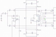
Now that you mentioned it, I recall some other experiments I did and indeed, there are better ways to compensate the loop. Unfortunately there's not much option for the LM4702 but I was able to find a schematic fragment that illustrates what I was playing with last year - attached.
The LT1166 model that I posted is correct and works fine with PSpice. I suppose other simulators may have problems in parsing device relative area parameters. Here's the original model I got from LT:
*
***
*
.subckt LT1166 1 2 3 4 5 6 7 8
Q4 N001 N005 N002 0 PN
Q3 N049 N005 3 0 PN m=5
Q1 N003 N007 N004 0 NP
Q2 N007 N013 3 0 NP m=5
R1 2 N004 200
R2 N002 2 200
Q5 3 N001 4 0 NP m=40
Q6 N002 N001 4 0 NP
Q7 N005 N008 N006 0 NP
R3 4 N006 1k
Q8 N008 N008 N009 0 NP m=2
R4 4 N009 500
R5 N008 N012 425
Q9 N010 N008 N011 0 NP
R6 4 N011 1k
Q10 1 N024 4 0 NP m=20
Q40 3 N003 1 0 PN m=40
Q39 N004 N003 1 0 PN
Q11 N022 N014 N023 0 NP
Q12 N017 N014 4 0 NP
Q13 N014 N015 4 0 NP
Q14 N015 N015 4 0 NP
Q15 N019 N008 N021 0 NP
Q16 1 N048 N001 0 NP
Q17 N048 N020 N019 0 PN
R7 4 N024 1.2k
R8 4 N023 160
R9 N022 N025 120
R10 4 N021 1k
R11 N018 5 5k
R12 N019 3 6k
R13 N017 3 1k
Q18 N015 N017 N016 0 PN
Q19 N014 N018 N016 0 PN
R28 N020 6 200
Q20 N025 N022 3 0 PN
Q21 4 N025 N026 0 PN m=10
Q22 N037 N027 N026 0 NP m=10
Q23 N027 N029 3 0 NP
C3 N018 N014 5p
Q24 N046 N028 N010 0 NP
Q25 N047 N031 N010 0 NP
Q26 N032 N034 N033 0 NP
Q27 4 N032 N003 0 PN
Q28 N033 N040 N035 0 PN
R14 3 N031 1k
R15 3 N033 6k
R16 N028 8 5k
R17 N035 1 1k
R18 N036 1 160
R19 N027 N029 120
R20 N030 1 1k
R21 N038 1 10
R22 N045 1 1k
R23 N044 1 1k
R24 N040 1 2k
R25 N041 1 1k
R26 N039 1 1k
R27 N034 7 200
Q29 N047 N047 1 0 PN
Q30 N046 N047 1 0 PN
Q31 N031 N046 1 0 PN
Q32 N029 N046 N036 0 PN
Q33 N037 N040 N030 0 PN
Q34 N024 N037 N038 0 PN
Q35 N016 N040 N045 0 PN
Q36 N043 N040 N044 0 PN
Q37 N042 N040 N041 0 PN
Q38 N013 N040 N039 0 PN
Q41 4 N042 N040 0 PN
Q42 N042 N043 N012 0 NP m=10
Q43 N043 N043 N008 0 NP
C2 N046 N028 5p
C1 N037 N024 20p
R29 N007 N013 200
R30 N005 N049 200
D1 3 N050 DZ
D2 4 N051 DZ
D3 1 N050 DD
D4 3 N051 DD
R31 1 N032 200k
R32 N048 4 200k
R33 N042 N008 10Meg
.model DD D(Is=2.52n Rs=0.568 N=1.752 Cjo=4p M=.4 Tt=20n)
.model DZ D(Is=0.6u Rs=.5 Cjo=150p nbv=5 bv=12 Ibv=1m)
.model NP NPN(BF=125 Cje=.5p Cjc=.5p Rb=500)
.model PN PNP(BF=125 Cje=.5p Cjc=.5p Rb=500)
.ends LT1166
Bob Cordell said:
One important trick is how we apply the global feedback compensation. This is one area in which my approach differs a bit from that of syn08. He takes his Miller compensation 47 pF capacitor from one side of the LT1166. This is not optimum. That approach only works optimally for a non-signal-dependent bias spread. With the LT1166 we have a signal-dependent bias spread. This might explain experiences wherein the distortion increases at higher frequencies.
Now that you mentioned it, I recall some other experiments I did and indeed, there are better ways to compensate the loop. Unfortunately there's not much option for the LM4702 but I was able to find a schematic fragment that illustrates what I was playing with last year - attached.
The LT1166 model that I posted is correct and works fine with PSpice. I suppose other simulators may have problems in parsing device relative area parameters. Here's the original model I got from LT:
*
***
*
.subckt LT1166 1 2 3 4 5 6 7 8
Q4 N001 N005 N002 0 PN
Q3 N049 N005 3 0 PN m=5
Q1 N003 N007 N004 0 NP
Q2 N007 N013 3 0 NP m=5
R1 2 N004 200
R2 N002 2 200
Q5 3 N001 4 0 NP m=40
Q6 N002 N001 4 0 NP
Q7 N005 N008 N006 0 NP
R3 4 N006 1k
Q8 N008 N008 N009 0 NP m=2
R4 4 N009 500
R5 N008 N012 425
Q9 N010 N008 N011 0 NP
R6 4 N011 1k
Q10 1 N024 4 0 NP m=20
Q40 3 N003 1 0 PN m=40
Q39 N004 N003 1 0 PN
Q11 N022 N014 N023 0 NP
Q12 N017 N014 4 0 NP
Q13 N014 N015 4 0 NP
Q14 N015 N015 4 0 NP
Q15 N019 N008 N021 0 NP
Q16 1 N048 N001 0 NP
Q17 N048 N020 N019 0 PN
R7 4 N024 1.2k
R8 4 N023 160
R9 N022 N025 120
R10 4 N021 1k
R11 N018 5 5k
R12 N019 3 6k
R13 N017 3 1k
Q18 N015 N017 N016 0 PN
Q19 N014 N018 N016 0 PN
R28 N020 6 200
Q20 N025 N022 3 0 PN
Q21 4 N025 N026 0 PN m=10
Q22 N037 N027 N026 0 NP m=10
Q23 N027 N029 3 0 NP
C3 N018 N014 5p
Q24 N046 N028 N010 0 NP
Q25 N047 N031 N010 0 NP
Q26 N032 N034 N033 0 NP
Q27 4 N032 N003 0 PN
Q28 N033 N040 N035 0 PN
R14 3 N031 1k
R15 3 N033 6k
R16 N028 8 5k
R17 N035 1 1k
R18 N036 1 160
R19 N027 N029 120
R20 N030 1 1k
R21 N038 1 10
R22 N045 1 1k
R23 N044 1 1k
R24 N040 1 2k
R25 N041 1 1k
R26 N039 1 1k
R27 N034 7 200
Q29 N047 N047 1 0 PN
Q30 N046 N047 1 0 PN
Q31 N031 N046 1 0 PN
Q32 N029 N046 N036 0 PN
Q33 N037 N040 N030 0 PN
Q34 N024 N037 N038 0 PN
Q35 N016 N040 N045 0 PN
Q36 N043 N040 N044 0 PN
Q37 N042 N040 N041 0 PN
Q38 N013 N040 N039 0 PN
Q41 4 N042 N040 0 PN
Q42 N042 N043 N012 0 NP m=10
Q43 N043 N043 N008 0 NP
C2 N046 N028 5p
C1 N037 N024 20p
R29 N007 N013 200
R30 N005 N049 200
D1 3 N050 DZ
D2 4 N051 DZ
D3 1 N050 DD
D4 3 N051 DD
R31 1 N032 200k
R32 N048 4 200k
R33 N042 N008 10Meg
.model DD D(Is=2.52n Rs=0.568 N=1.752 Cjo=4p M=.4 Tt=20n)
.model DZ D(Is=0.6u Rs=.5 Cjo=150p nbv=5 bv=12 Ibv=1m)
.model NP NPN(BF=125 Cje=.5p Cjc=.5p Rb=500)
.model PN PNP(BF=125 Cje=.5p Cjc=.5p Rb=500)
.ends LT1166
Attachments
Re: LT1166
Huh? Modulation of Vbias has definitely an effect on the transmission, because it alters the gm of the output stage.
Here some figures from my "armchair":
Circuit: NFB output stage
Devices: 2SJ201/2SK1530
Iq = 150mA
Po=50W in 8 Ohm
With fixed Vbias THD20=34ppm
With fixed Id product THD20=103ppm
Cheers, Edmond.
Bob Cordell said:[snip]
One thing to realize is that, acting only as a dynamic bias spreader, it should have virtually no effect on the transmission of the program signal to the output stage.
[snip]
Cheers,
Bob
Huh? Modulation of Vbias has definitely an effect on the transmission, because it alters the gm of the output stage.
Here some figures from my "armchair":
Circuit: NFB output stage
Devices: 2SJ201/2SK1530
Iq = 150mA
Po=50W in 8 Ohm
With fixed Vbias THD20=34ppm
With fixed Id product THD20=103ppm
Cheers, Edmond.
- Home
- Amplifiers
- Solid State
- Bob Cordell Interview: Error Correction