traderbam said:Jan, [snip]I think you want there to be something superior about HEC in terms of how the output error is corrected but there isn't. The only difference is HEC uses PFB to generate forward gain.
Brian
No, I don't see one or the other as 'superior'. Either can be implemented in a good sounding amplifier. Neither can be implemented as a true practical zero distortion amplifier.
And yes the 'infinite gain' is generated differently. In traditional nfb, it is approached, asymptotically, by maximizing loop gain. In HEC, it is actually in theory, mathematically, reached.
The reason I am playing with HEC is not that I consider it superior in its results, but I find it an elegant way to build a good amp. It's somthing different, some new things to solve, and I like that.
Jan Didden
In a practical circuit the output error reduction is primarily limited by the bandwidth and linearity of the output stage transistors whose error you are trying to correct.
This means that in either case the forward gain can be a pure integrator at best...huge gain at dc and unity gain dtermined by the bandwidth of the output stage.
An integrator can be achieved without a PFB loop. Standard op-amps do this with a VAS stage and miller cap. You can also make an integrator with an op-amp with cap from output to inverting input. It may be simpler to make an integrator with PFB, especially if you want extremely high dc gain.
In practical output stages huge dc gain is not required. A feedback loop gain of 30dB to 50dB is adequate. Indeed, there are many in this forum who believe that the OL gain of a circuit should be flat across the audio band and that steadily decreasing gain (and associated phase shift) causes sonic problems. In this case the designer might want to keep the OL gain flat at say 40dB from dc to 100kHz or more. In which case the PFB circuit needs to be gain limited (de-tuned from the so-called "null").
I also remind everyone that measures of THD are not that well correlated with sound quality. There is much more to it than that as any low-feedback or tube designer will tell you. Setting your PFB gain for minimum THD is no guarantee of best sound quality.
traderbam said:In a practical circuit the output error reduction is primarily limited by the bandwidth and linearity of the output stage transistors whose error you are trying to correct.
This means that in either case the forward gain can be a pure integrator at best...huge gain at dc and unity gain dtermined by the bandwidth of the output stage.
An integrator can be achieved without a PFB loop. Standard op-amps do this with a VAS stage and miller cap. You can also make an integrator with an op-amp with cap from output to inverting input. It may be simpler to make an integrator with PFB, especially if you want extremely high dc gain.
In practical output stages huge dc gain is not required. A feedback loop gain of 30dB to 50dB is adequate. Indeed, there are many in this forum who believe that the OL gain of a circuit should be flat across the audio band and that steadily decreasing gain (and associated phase shift) causes sonic problems. In this case the designer might want to keep the OL gain flat at say 40dB from dc to 100kHz or more. In which case the PFB circuit needs to be gain limited (de-tuned from the so-called "null").
I also remind everyone that measures of THD are not that well correlated with sound quality. There is much more to it than that as any low-feedback or tube designer will tell you. Setting your PFB gain for minimum THD is no guarantee of best sound quality.
One ot the things I like in HEC is that the forward gain need not be more than the CL gain. This lets you build a simple, wide band, relatively linear amp with low OL gain. No need to resort to very high OL gain and low OL bandwidth to satisfy the nfb paradigm. As I said, it's a different and interesting way of doing things.
Jan Didden
It depends what one includes as "theoretically possible". If you say an infinite gain block is not theoretically possible but a PFB loop with gain = 1 is then I understand. 🙂And yes the 'infinite gain' is generated differently. In traditional nfb, it is approached, asymptotically, by maximizing loop gain. In HEC, it is actually in theory, mathematically, reached.
Neither can zero the output error, even in theory, if the amplifier has finite bandwidth and is non-linear because of stability. A FF network can, in theory, zero the output error because the amplifier characteristic is not part of the correction equation.
Jan, I agree as long as you are careful not to assume the closed loop circuit is more stable just because the OL amplifer gain is low. When the feedback network is added everything changes. The stability is now determined by the CL, feedback loop gain, which is typically very high.One ot the things I like in HEC is that the forward gain need not be more than the CL gain. This lets you build a simple, wide band, relatively linear amp with low OL gain.
Edmond Stuart said:
Hi Adam,
Here's a alternative circuit. It differs from HEC in that it doesn't subtract the error signal from the input, in stead, the error signal is inverted first by means of the I-mirrors and then added to the input signal. In doing so, no bias voltage (22V or so) is stolen from the VAS, thus no need for a boosted power supply for the front-end.
OTOH, the output voltage is slightly limited, because the drivers are also fed from the same power supply. But who cares, as the last few volts from a vertical MOSFET are problematic anyhow, as in this region Cgd is sky-rocketing. THD20 = 30ppm (according my sim).
Cheers, Edmond.
Edmond, Would you mind adding a small resistor in series with zener diode and checking how the stuff behaves?
regards
Adam
darkfenriz said:Edmond, Would you mind adding a small resistor in series with zener diode and checking how the stuff behaves?
regards
Adam
Hi Adam,
Of course, but why? Do you have something particular in mind?
Cheers, Edmond.
I guess more current though q6/q7 may result in higher current though zener diode which can result in higher current though q6/q7, sort of positive bias point feedback,
just a thought, not sure about that.
cheers
just a thought, not sure about that.
cheers
darkfenriz said:I guess more current though q6/q7 may result in higher current though zener diode which can result in higher current though q6/q7, sort of positive bias point feedback,
just a thought, not sure about that.
cheers
Hi Adam,
No, it doesn't work that way. A small resistor in series with the zener effectively increases the bias voltage and indeed, Ic of Q6/Q7 increases too (and Iq of the OP-stage!), but this increase is not reflected back into the zener, rather into Ic of Q1/Q2. So, there's no 'escalation' due to positive feedback.
The zener current is (mainly) determined by the current through R8. BTW, the latter ensures a proper startup. Without this resistor all currents stay zero.
Also notice the twofold role of Q6/Q7. They serve as emitter follower and as sensing tranny as well.
Cheers, Edmond.
PS: Adam and lumanauw, thanks for your interest.
Edmond,
I have already told you that I find this an elegant and clever circuit. Are you planning to build it? Would be quite an interesting test to hear how such a circuit sounds.
Jan Didden
I have already told you that I find this an elegant and clever circuit. Are you planning to build it? Would be quite an interesting test to hear how such a circuit sounds.
Jan Didden
janneman said:Edmond,
I have already told you that I find this an elegant and clever circuit.
Thanks!
Are you planning to build it? Would be quite an interesting test to hear how such a circuit sounds.
Jan Didden
Hi Jan,
I have no plans to build it yet. If I'm building something then it is a TMC amplifier in the first place to see if that concept is competitive with EC. If it fails, then perhaps I will build this modified EC circuit.
The problem is that I don't have the machinery any longer to build (professional looking) amplifiers. But maybe others are willing to build the circuit.
How it will sound? I think almost the same as any other EC amp if all specs like THD, IMD and BW are equal and the same output devices are used etc. I don't think it is much better than HEC in terms of 'sound' quality. As I said before, the main advantage is that one doesn't need a boosted power supply for the front-end. The other advantage is that the distortion of the drivers is also compensated, that's all.
No, that's not all. Opposed to HEC, the bias generator works completely independent from the rest, so one can easily adapt it to one's own needs.
Cheers, Edmond.
What the HEC...
Yes! We could compare my ec amp with your tmc amp! 😉
This is not 'opposed to HEC', but depends on the particular implementation. My HEC amp also has a bias generator that is completely independent of the HEC circuit.
Jan Didden
Edmond Stuart said:[snip] If I'm building something then it is a TMC amplifier in the first place to see if that concept is competitive with EC. [snip]Cheers, Edmond.
Yes! We could compare my ec amp with your tmc amp! 😉
Edmond Stuart said:[snip]Opposed to HEC, the bias generator works completely independent from the rest, so one can easily adapt it to one's own needs.
Cheers, Edmond.
This is not 'opposed to HEC', but depends on the particular implementation. My HEC amp also has a bias generator that is completely independent of the HEC circuit.
Jan Didden
Re: What the HEC...
 Your 'HEC' is not just HEC, but DEC, from Didden EC. 😉
janneman said:This is not 'opposed to HEC', but depends on the particular implementation. My HEC amp also has a bias generator that is completely independent of the HEC circuit.
Jan Didden
Your 'HEC' is not just HEC, but DEC, from Didden EC. 😉Re: Re: This is why I consider FB and FF to be chalk and cheese
Hi Brian,
I think this is the post you were referring to in your email that I received. It was in response to your post #2385. I understand why this post of mine upset you.
I apologize for being too dismissive of your point.
Our differences do remain, and it seems they are unlikely to be resolved. In regard to the theory of HEC, you seems to believe solely in the feedback-only way of looking at it, which is a perfectly valid way to look at it that I have never denied. On the other hand, I allow for the value of looking at it in the original way Hawksford described it, in the feedback-only way, and in the small positive-or-negative feedback way that I think Jan prefers. I just believe that each of these viewpoints is equivalent if looked at properly, and that each has useful insight to provide.
We also seem to differ in our view of HEC versus true feedforward error correction. You seem to argue that true FF EC is better than HEC, and you are right, on paper. On the other hand, I wish FF EC were that good in practice, but I just don't know how to get around the practical issue of distortion introduced by the summer. I would certainly advocate true FF EC if it could be accomplished in a practical way that could provide results equal to or better than HEC in the real world. Absent a good summer, I just think that talking too much abou the merits of true FF EC over HEC is just academic. I guess that is where we stand, and that probably will not change.
Once again, I apologize for dismissing your point the way that I did.
Cheers,
Bob
Bob Cordell said:
Duh!
This proves nothing we did not know already.
Yes, Brian, if you have an ideal summer at the output, feedforward error correction is better than HEC, and theoretically perfect.
Why don't you do some work on that output summer.
Cheers,
Bob
Hi Brian,
I think this is the post you were referring to in your email that I received. It was in response to your post #2385. I understand why this post of mine upset you.
I apologize for being too dismissive of your point.
Our differences do remain, and it seems they are unlikely to be resolved. In regard to the theory of HEC, you seems to believe solely in the feedback-only way of looking at it, which is a perfectly valid way to look at it that I have never denied. On the other hand, I allow for the value of looking at it in the original way Hawksford described it, in the feedback-only way, and in the small positive-or-negative feedback way that I think Jan prefers. I just believe that each of these viewpoints is equivalent if looked at properly, and that each has useful insight to provide.
We also seem to differ in our view of HEC versus true feedforward error correction. You seem to argue that true FF EC is better than HEC, and you are right, on paper. On the other hand, I wish FF EC were that good in practice, but I just don't know how to get around the practical issue of distortion introduced by the summer. I would certainly advocate true FF EC if it could be accomplished in a practical way that could provide results equal to or better than HEC in the real world. Absent a good summer, I just think that talking too much abou the merits of true FF EC over HEC is just academic. I guess that is where we stand, and that probably will not change.
Once again, I apologize for dismissing your point the way that I did.
Cheers,
Bob
Thanks for the apology, Bob. I should say that I didn't cite this post in my email nor did it or any other posts upset me, including the ones I explicitly referenced in my email. However, I appreciate the sentiment and extend goodwill to you too.
For the reasons I explained in my email I would like to try to stick to objective reasoning.
Now, when I read Hawkford I get a different message. I think Hawksford's original 1981 paper was a little loose in its claims but he went on to tighten it all up in his paper "Towards a Generation of Error Correction Amplifiers" written in 1991:
Hawksford publications
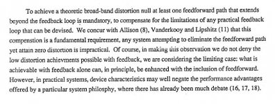
Hawksford does not mix up FB and FF. He understands that error elimination, or nulling, using feedback requires infinite gain and is therefore impractical in both theory and practice when applied to a non-linear, speed limited amplifier.
For the reasons I explained in my email I would like to try to stick to objective reasoning.
Now, when I read Hawkford I get a different message. I think Hawksford's original 1981 paper was a little loose in its claims but he went on to tighten it all up in his paper "Towards a Generation of Error Correction Amplifiers" written in 1991:
Hawksford publications
Hawksford does not mix up FB and FF. He understands that error elimination, or nulling, using feedback requires infinite gain and is therefore impractical in both theory and practice when applied to a non-linear, speed limited amplifier.
Attachments
Re: Re: Re: This is why I consider FB and FF to be chalk and cheese
Hi Bod,
In other words, where to break the loop, right?
I like to add that breaking the loop at any place is always valid as long as what is claimed is in accordance with the properties of the loop broken at that specific location. That's rather obvious of course.
But that's not the point, rather, how can we find the most useful and characteristic information. As I have already demonstrated (see post 2148 and 2175), this can be found if we break the loop at the output summer. The Bode plot thus obtained tells us exactly how large the phase margin is and how much HD reduction we can expect. Breaking the loop at any other location, no matter how valid it is, does not provide this essential information.
Cheers, Edmond.
Bob Cordell said:Hi Brian,
.....................
Our differences do remain, and it seems they are unlikely to be resolved. In regard to the theory of HEC, you seems to believe solely in the feedback-only way of looking at it, which is a perfectly valid way to look at it that I have never denied. On the other hand, I allow for the value of looking at it in the original way Hawksford described it, in the feedback-only way, and in the small positive-or-negative feedback way that I think Jan prefers. I just believe that each of these viewpoints is equivalent if looked at properly, and that each has useful insight to provide.
...........................
Cheers, Bob
Hi Bod,
In other words, where to break the loop, right?
I like to add that breaking the loop at any place is always valid as long as what is claimed is in accordance with the properties of the loop broken at that specific location. That's rather obvious of course.
But that's not the point, rather, how can we find the most useful and characteristic information. As I have already demonstrated (see post 2148 and 2175), this can be found if we break the loop at the output summer. The Bode plot thus obtained tells us exactly how large the phase margin is and how much HD reduction we can expect. Breaking the loop at any other location, no matter how valid it is, does not provide this essential information.
Cheers, Edmond.
traderbam said:Thanks for the apology, Bob. I should say that I didn't cite this post in my email nor did it or any other posts upset me, including the ones I explicitly referenced in my email. However, I appreciate the sentiment and extend goodwill to you too.
For the reasons I explained in my email I would like to try to stick to objective reasoning.
Now, when I read Hawkford I get a different message. I think Hawksford's original 1981 paper was a little loose in its claims but he went on to tighten it all up in his paper "Towards a Generation of Error Correction Amplifiers" written in 1991:
Hawksford publications
Hawksford does not mix up FB and FF. He understands that error elimination, or nulling, using feedback requires infinite gain and is therefore impractical in both theory and practice when applied to a non-linear, speed limited amplifier.
Hi Brian,
I don't disagree with anything Hawksford has said there. To get a theoretical BROADBAND null, you need feedforward. To get a wonderfully deep and useful minima over the full audio band, all you need is HEC. The theoretical BROADBAND null whereof Hawksford speaks is attainable only in theory with FF EC due to the lack of a perfect summer through which the output power can flow. That's pretty much where I come down on this.
While I do have some whit, I am not a very good comedian 🙂.
Cheers,
Bob
Re: Re: Re: Re: This is why I consider FB and FF to be chalk and cheese
Yep. The simulation plot I showed where I broke the loop several posts ago is a good representation of the feed-back-only view, and does claerly show loop gain and phase margin. It is a very useful way to look at EC. Its just not the only way. That's my only point. Whatever floats your boat...
Cheers,
Bob
Edmond Stuart said:
Hi Bod,
In other words, where to break the loop, right?
I like to add that breaking the loop at any place is always valid as long as what is claimed is in accordance with the properties of the loop broken at that specific location. That's rather obvious of course.
But that's not the point, rather, how can we find the most useful and characteristic information. As I have already demonstrated (see post 2148 and 2175), this can be found if we break the loop at the output summer. The Bode plot thus obtained tells us exactly how large the phase margin is and how much HD reduction we can expect. Breaking the loop at any other location, no matter how valid it is, does not provide this essential information.
Cheers, Edmond.
Yep. The simulation plot I showed where I broke the loop several posts ago is a good representation of the feed-back-only view, and does claerly show loop gain and phase margin. It is a very useful way to look at EC. Its just not the only way. That's my only point. Whatever floats your boat...
Cheers,
Bob
A pretty exhausting look at feed forward by Stochino was published around 1994 I think, by EW & WW. There is a link to the article on my home page, which I repeat here:
Audio design leaps forward?
Good bedtime reading 😉
Jan Didden
Audio design leaps forward?
Good bedtime reading 😉
Jan Didden
- Home
- Amplifiers
- Solid State
- Bob Cordell Interview: Error Correction