Re: Re: Re: Real World Implementations
Hi Pete,
It seems that you are overlooking an important aspect of the practical implementation of HEC. The limiting factor is the phase shift from the driver, the output trannies and the parasitic lead inductance. Consequently, some form of frequency compensation is mandatory, which sets the bandwidth of the correction circuit to 10MHz at maximum (in Bob's EC-amp it is set at 3.4MHz).
So, it doesn't help using 100, 300 or even 1000MHz trannies in the correction circuit. This bandwidth limitation also implies that the 3rd harmonic of 20kHz, for example, cannot be reduced by more than some 43dB.
Regarding Cherry's implementation (i.e. including the output stage in the Miller FB loop), it is the same limiting factor that can make his topology unstable. But also in this case, one can and should apply some kind of frequency compensation that limits the bandwidth of the FB signal obtained directly from the output. A trick that do just that is called "Transitional Miller Compensation" (TMC) and it can be proved that it does the same job as HEC, provided that Ft of the TMC low pass filter is set at the same value as in HEC.
Cheers, Edmond.
PS: I refuse to build a TMC amp, just to convince people. My simulations, which are damn reliable, are convincing enough.😀
PB2 said:...................
It's clear that traditional negative feedback systems do not even come close to infinite gain, especially at 20 KHz. Indeed, this is not even generally a goal due to the conflicting requirement for stability. EC on the other hand adds small 100 to 300 MHz transistors which provide huge margin over the 20 KHz bandwidth for audio, and therefore as Bob points out there is a deep null (obviously not a perfect null, but what we call in engineering a null) over the audio band. Contrast this with traditional negative feedback amplifiers which do not even come close to inifinite gain over the audio band. This is why I view the reduction argument offered to be obviously flawed. The details are in the implementation differences as I see it, and this is why the implementation details cannot be casually dismissed.
I'm somewhat familiar with Cherry's work, having been a member of the AES for over 20 years, however I've not read those papers probably since they were published. It's certainly possible to put negative feedback around the output stage. I don't dispute this, I would question if there is an implementation that does as good a job as EC with equal or lesser complexity.
Pete B.
Hi Pete,
It seems that you are overlooking an important aspect of the practical implementation of HEC. The limiting factor is the phase shift from the driver, the output trannies and the parasitic lead inductance. Consequently, some form of frequency compensation is mandatory, which sets the bandwidth of the correction circuit to 10MHz at maximum (in Bob's EC-amp it is set at 3.4MHz).
So, it doesn't help using 100, 300 or even 1000MHz trannies in the correction circuit. This bandwidth limitation also implies that the 3rd harmonic of 20kHz, for example, cannot be reduced by more than some 43dB.
Regarding Cherry's implementation (i.e. including the output stage in the Miller FB loop), it is the same limiting factor that can make his topology unstable. But also in this case, one can and should apply some kind of frequency compensation that limits the bandwidth of the FB signal obtained directly from the output. A trick that do just that is called "Transitional Miller Compensation" (TMC) and it can be proved that it does the same job as HEC, provided that Ft of the TMC low pass filter is set at the same value as in HEC.
Cheers, Edmond.
PS: I refuse to build a TMC amp, just to convince people. My simulations, which are damn reliable, are convincing enough.😀
Re: Re: Re: Real World Implementations
Well stated, Pete.
Bob
PB2 said:
I don't require you to abandon valid system transformations, simply the view that a specific and different implementation such as EC can be dismissed as equivalent to traditional negative feedback. Perhaps we should just agree to disagree.
I've tried to be very careful with my wording not to assert that EC is perfect, obviously nothing is perfect. I disagree with your claim that the non-ideal characteristics of EC are the same as the impossiblity of infinite gain. Obviously, no circuit or design on paper can be implemented exactly, since all real world designs are subject to tolerances, finite bandwidth etc. you certainly know this. Thus, for any real world implementation we might ask how close does this come to the mathematical model.
It's clear that traditional negative feedback systems do not even come close to infinite gain, especially at 20 KHz. Indeed, this is not even generally a goal due to the conflicting requirement for stability. EC on the other hand adds small 100 to 300 MHz transistors which provide huge margin over the 20 KHz bandwidth for audio, and therefore as Bob points out there is a deep null (obviously not a perfect null, but what we call in engineering a null) over the audio band. Contrast this with traditional negative feedback amplifiers which do not even come close to inifinite gain over the audio band. This is why I view the reduction argument offered to be obviously flawed. The details are in the implementation differences as I see it, and this is why the implementation details cannot be casually dismissed.
I'm somewhat familiar with Cherry's work, having been a member of the AES for over 20 years, however I've not read those papers probably since they were published. It's certainly possible to put negative feedback around the output stage. I don't dispute this, I would question if there is an implementation that does as good a job as EC with equal or lesser complexity.
Pete B.
Well stated, Pete.
Bob
traderbam said:Bob wrote:
According to Stereophile the output Z is not much less than 0.1 across the audio band.
I wonder if it is more to do with their OS. It could be the SMPS if they don't use large caps on the output. It might be the OS devices they are using are weedy. It could also be that their feedback circuit, which is floating and has quite limited voltage headroom (10V is it?), may not be able to drive enough Vgs on the output FETs to get more than 15A peak.
It think it is rather odd for a big amp to have a 15A peak limit. Usually, as you mention, there would be a much higher peak but a sustained level limit. In these cases a mfr is not likely to make such a bunch of excuses about it as Halcro do in their manual.
Stereophiles OP Z measurements appear to be bogus,
unfortunately. They usually state that it includes speaker cable.
cheers
Terry
Thanks for pointing that out, Terry.
Having said this I looked at a few other reviews and it appears that Stereophile's output Z measurements are regularly different from the mfr spec.
The Krell Evolution 600 (us$30000/pair), 600W, 50A peak current
claims 0.03 ohms output resistance. Stereophile says:
The Mark Levinson 431 (us$6000/stereo), 200W, 26A peak current claims 0.02 ohms. Stereophile measures 0.08 ohms.
The Bryston 14B-SST (us$6000/stereo), 600W, 26A peak current claims 0.03 ohms. Stereophile measure 0.12 ohms rising to 0.21 ohms at 20kHz.
The Pass Labs XA160 (us$18000/pair), 118W, claims 0.27 ohms.
Stereophile measure 0.57ohms rising to 0.80 ohms at 20kHz. 5.4A peak current.
The review of the Halcro goes on to say:
This begs the question of how resistive their 6 foot length of cable was. They don't say but I would expect it to be no more than 10 or 20 milliohms.From Stereophile Aug 2006:
The dm88's output impedance was very low across almost all the audioband, at 0.1 ohm including 6' of multistrand speaker cable. It rose slightly at 20kHz, to 0.14 ohm, though the increase is iinsignificant.
Having said this I looked at a few other reviews and it appears that Stereophile's output Z measurements are regularly different from the mfr spec.
The Krell Evolution 600 (us$30000/pair), 600W, 50A peak current
claims 0.03 ohms output resistance. Stereophile says:
My
measurement of the 600's output impedance was 0.124 ohm, which is higher than the specified figure. My measurement does include 6' of cable, though this should account for no more than a small fraction of the difference.
The Mark Levinson 431 (us$6000/stereo), 200W, 26A peak current claims 0.02 ohms. Stereophile measures 0.08 ohms.
The Bryston 14B-SST (us$6000/stereo), 600W, 26A peak current claims 0.03 ohms. Stereophile measure 0.12 ohms rising to 0.21 ohms at 20kHz.
The Pass Labs XA160 (us$18000/pair), 118W, claims 0.27 ohms.
Stereophile measure 0.57ohms rising to 0.80 ohms at 20kHz. 5.4A peak current.
The review of the Halcro goes on to say:
The Halcro dm88 (us$40000/pair) is a 270W amp with peak current of 15A. Halcro don't specify output Z. Stereophile measure 0.1 ohms rising to 0.14 at 20kHz.The measured output power at 1% THD+N was greater than specified, at 295W into 8 ohms (24.7dBW) and 525W into 4 ohms (24.2dBW). The dm88 is less happy driving 2 ohms, however, clipping at 266W (18.2dBW).
Re: Re: Re: Re: Real World Implementations

Bob Cordell said:
Well stated, Pete.
Bob
Re: Re: Re: Re: Real World Implementations
You make assumptions hoping to prove that I am wrong, please stop making assumptions about my reasoning. I suggest that you ask in the future. I consulted for a small group within a multi-billion dollar company on modelling bonding wire effects, lead frame effects and of course, lead and interconnect effects in high speed circuits. These circuits had edge speeds well under a nanosecond. No I did not overlook the lead effects.
You don't recognize that 3.4 MHz bandwidth is huge margin over 20 KHz? You don't find a reduction of 43 dB to be enough? I could see where if it was 100 dB, you'd probably demand 150 or 200 dB and this is why I don't see this as reasonable discussion. I'm not going to waste my time arguing, the fact that Bob's amp produces a decent null proves to me that there is enough margin in his real world implementation. If you claim that there is something specifically wrong with Bob's design/prototype why don't you state it clearly.
Further, and perhaps more important, Bob comes here and generously gives his time. Remember Bob, wrote the article in a peer reviewed journal, built and tested a prototype to prove out his design and concepts. And you refuse to build your circuits claiming that your simulations are "damn reliable". Note that one person who built one of your designs found distortion well above your simulated claims.
Others here insist that Bob's design cannot be stable, did they miss the fact that he built and tested a prototype? It seems that their fear of positive feedback has caused them to loose their grip on reality. Behavior like this makes me find public forums such as this more entertaining than productive. It is unfortunate.
I would not call Cherry's nested feedback where he includes the OS in the Miller loop local feedback to the output stage. I would be concerned about large signal performance under real world conditions where the output stage clips. These non-linear effects are difficult to simulate accurately. There's much more to consider in real world designs than the more simplistic models that you demand prove that you are correct. I certainly use such models, however I keep in mind that there is more to be tested through prototyping. Have you built a prototype and tested it under mis-use conditions?
I don't want to get into a back and forth with you Edmond as I think we have very different perspectives. I always wonder about a person's background when I strongly disagree just to understand them better. Do you have an engineering bio posted somewhere?
Pete B.
Edmond Stuart said:
Hi Pete,
It seems that you are overlooking an important aspect of the practical implementation of HEC. The limiting factor is the phase shift from the driver, the output trannies and the parasitic lead inductance. Consequently, some form of frequency compensation is mandatory, which sets the bandwidth of the correction circuit to 10MHz at maximum (in Bob's EC-amp it is set at 3.4MHz).
So, it doesn't help using 100, 300 or even 1000MHz trannies in the correction circuit. This bandwidth limitation also implies that the 3rd harmonic of 20kHz, for example, cannot be reduced by more than some 43dB.
Regarding Cherry's implementation (i.e. including the output stage in the Miller FB loop), it is the same limiting factor that can make his topology unstable. But also in this case, one can and should apply some kind of frequency compensation that limits the bandwidth of the FB signal obtained directly from the output. A trick that do just that is called "Transitional Miller Compensation" (TMC) and it can be proved that it does the same job as HEC, provided that Ft of the TMC low pass filter is set at the same value as in HEC.
Cheers, Edmond.
PS: I refuse to build a TMC amp, just to convince people. My simulations, which are damn reliable, are convincing enough.😀
You make assumptions hoping to prove that I am wrong, please stop making assumptions about my reasoning. I suggest that you ask in the future. I consulted for a small group within a multi-billion dollar company on modelling bonding wire effects, lead frame effects and of course, lead and interconnect effects in high speed circuits. These circuits had edge speeds well under a nanosecond. No I did not overlook the lead effects.
You don't recognize that 3.4 MHz bandwidth is huge margin over 20 KHz? You don't find a reduction of 43 dB to be enough? I could see where if it was 100 dB, you'd probably demand 150 or 200 dB and this is why I don't see this as reasonable discussion. I'm not going to waste my time arguing, the fact that Bob's amp produces a decent null proves to me that there is enough margin in his real world implementation. If you claim that there is something specifically wrong with Bob's design/prototype why don't you state it clearly.
Further, and perhaps more important, Bob comes here and generously gives his time. Remember Bob, wrote the article in a peer reviewed journal, built and tested a prototype to prove out his design and concepts. And you refuse to build your circuits claiming that your simulations are "damn reliable". Note that one person who built one of your designs found distortion well above your simulated claims.
Others here insist that Bob's design cannot be stable, did they miss the fact that he built and tested a prototype? It seems that their fear of positive feedback has caused them to loose their grip on reality. Behavior like this makes me find public forums such as this more entertaining than productive. It is unfortunate.
I would not call Cherry's nested feedback where he includes the OS in the Miller loop local feedback to the output stage. I would be concerned about large signal performance under real world conditions where the output stage clips. These non-linear effects are difficult to simulate accurately. There's much more to consider in real world designs than the more simplistic models that you demand prove that you are correct. I certainly use such models, however I keep in mind that there is more to be tested through prototyping. Have you built a prototype and tested it under mis-use conditions?
I don't want to get into a back and forth with you Edmond as I think we have very different perspectives. I always wonder about a person's background when I strongly disagree just to understand them better. Do you have an engineering bio posted somewhere?
Pete B.
Re: Is the Earth round?
Hi Brian,
I like #6 the best. But I agree that it is subjective conjecture 🙂.
Seriously, I'd say that some of the items on that list are a bit more than subjective conjecture. But I'll admit that the Devil is always in the details and that implementation details are always important. All I can say is that in my own experience, HEC has been the best way to get the output stage distortion way down, as compared with negative feedback approaches or as compared with error feedforward.
This does not mean that there are not some bright people out there who can get the same or even better results with some form of feedback, such as TMC.
Indeed, if someone can demonstrate such low distortion from a MOSFET output stage biased at only 150 mA, and with as few or fewer components as HEC, I will indeed be the first to shake their hand.
If it's out there in a reasonable apples-apples comparison, I just haven't seen it. I'd love to see it. The same goes for any actual implementation of error feedforward.
Cheers,
Bob
traderbam said:Recent arguments in favour of EC being different from and superior to NFB:
Objective
There is a simple way to insert a pot to adjust for a THD minima.
Subjective conjecture
1) It cancels the output error just like feed-forward rather than reducing it
2) It enables the use of faster transistors in the correction circuit
3) The system is more stable because it has an open loop gain of <1
4) NFB requires infinite gain to eliminate the error. EC does not.
5) EC topology results in a simpler circuit
6) Bob Cordell says it is and he should know
Hi Brian,
I like #6 the best. But I agree that it is subjective conjecture 🙂.
Seriously, I'd say that some of the items on that list are a bit more than subjective conjecture. But I'll admit that the Devil is always in the details and that implementation details are always important. All I can say is that in my own experience, HEC has been the best way to get the output stage distortion way down, as compared with negative feedback approaches or as compared with error feedforward.
This does not mean that there are not some bright people out there who can get the same or even better results with some form of feedback, such as TMC.
Indeed, if someone can demonstrate such low distortion from a MOSFET output stage biased at only 150 mA, and with as few or fewer components as HEC, I will indeed be the first to shake their hand.
If it's out there in a reasonable apples-apples comparison, I just haven't seen it. I'd love to see it. The same goes for any actual implementation of error feedforward.
Cheers,
Bob
It looks like Cherry’s “Nests” can spot Bob’s EC 2-3 transistors and win in sim
I took the input and power output stage from my earlier sim of Bob’s EC circuit
http://www.diyaudio.com/forums/showthread.php?s=&postid=1072546&highlight=#post1072546
and naively cut in Cherry’s circuit from:
“Nested Differentiating Feedback Loops in Simple Audio Amplifiers”
JAES, Volume 30 Number 5 pp. 295-305; May 1982
“Many audio power amplifiers consist in essence of a long-tailed-pair first stage, a lag-compensated common-emitter stage with its emitter on a supply rail, a complementary-emitter-follower output stage, and overall negative feedback. Two nested differentiating feedback loops can be added to this basic topology, to achieve between one and two orders of magnitude reduction in distortion, at little increase in component cost. Six extra components are essential; two small-signal transistors, one resistor, and two capacitors. Further small components such as zener diodes and bypass capacitors may be required, depending on the details of the supply rails the amplifier.”
Assuming Bob’s mosfet output stage must be 10x faster than Cherry’s example BJT circuit I simply scaled the Cherry nested differentiating time constants by 10x without further analysis, cascoded the VAS and then played some with gate stoppers and driver local comp caps to improve phase margin of the sim
I get equal distortion numbers from my sym of Bob’s EC circuit and Cherry’s simple nested feedback – with fewer transistors in the Cherry circuit - remember that the "macromodel" front end in the CordellMosfetAmp circuit includes the VAS too
Along the way to the complete Cherry circuit I used Spice CCS for R5 and the R6,7 bootstrap CCs which gave nearly an order of magnitude better simmed distortion – but the challenge was to minimize additional circuitry at the same performance…
I haven’t tried simmed clipping or many other tests that would give enough confidence to go forward with a hardware implementation but Cherry did build and measure his amp with the BJT output in his article
the BD139/140 models were added directly to my LtSpice and the Mosfet models have to be found, maybe tomorrow
Attachments
Sorry, but Cherry is every bit as much of a fraud as Otala was.
You're using the blatantly unstable Hawksford cascode, combined with the also blatantly unstable configuration advocated by Cherry of including the output stage in the Miller loop.
Have you got a real-world example, or are you just trolling?
You're using the blatantly unstable Hawksford cascode, combined with the also blatantly unstable configuration advocated by Cherry of including the output stage in the Miller loop.
Have you got a real-world example, or are you just trolling?
Re: Is the Earth round?
Says the person who has trouble understanding the meaning of the word null:
http://www.diyaudio.com/forums/showthread.php?postid=1309027#post1309027
And who has trouble understanding the term cancellation:
http://www.diyaudio.com/forums/showthread.php?postid=1313544#post1313544
You're not directing this at me are you traderbam? Because I would find it offensive that you put your own spin on my view, and I do not agree with most of your numbered list there.
It seems that your inability to see this design from the other valid perspectives has annoyed many people here:
http://www.diyaudio.com/forums/showthread.php?postid=1312196#post1312196
You seem to need to have the last word, I suggest that you drop it with me and we just agree to disagree.
I do recall you stating earlier that this was about implementation, then when you couldn't "win" that argument switched to claiming a system behavioral discussion. It is clear that you change the problem to fit your (incorrect) answer/view.
Where is the ignore feature on this forum?
Pete B.
traderbam said:Recent arguments in favour of EC being different from and superior to NFB:
Objective
There is a simple way to insert a pot to adjust for a THD minima.
Subjective conjecture
1) It cancels the output error just like feed-forward rather than reducing it
2) It enables the use of faster transistors in the correction circuit
3) The system is more stable because it has an open loop gain of <1
4) NFB requires infinite gain to eliminate the error. EC does not.
5) EC topology results in a simpler circuit
6) Bob Cordell says it is and he should know
Engineering has objective analysis as a basic tenet.
This is to stop our powerful motivations to believe (or to claim) something from blinding us to reality.
Just ask Aristotle.
😎
Says the person who has trouble understanding the meaning of the word null:
http://www.diyaudio.com/forums/showthread.php?postid=1309027#post1309027
And who has trouble understanding the term cancellation:
http://www.diyaudio.com/forums/showthread.php?postid=1313544#post1313544
You're not directing this at me are you traderbam? Because I would find it offensive that you put your own spin on my view, and I do not agree with most of your numbered list there.
It seems that your inability to see this design from the other valid perspectives has annoyed many people here:
http://www.diyaudio.com/forums/showthread.php?postid=1312196#post1312196
You seem to need to have the last word, I suggest that you drop it with me and we just agree to disagree.
I do recall you stating earlier that this was about implementation, then when you couldn't "win" that argument switched to claiming a system behavioral discussion. It is clear that you change the problem to fit your (incorrect) answer/view.
Where is the ignore feature on this forum?
Pete B.
andy_c said:You're using the blatantly unstable Hawksford cascode....
Hey? What? Huh? 😕
Andy, I've been using the Hawksford cascode and it works a treat - no blatant oscillations as far as I can see.
You are talking about the emitter referenced cascode transistor?
Cheers,
Glen
andy_c said:Sorry, but Cherry is every bit as much of a fraud as Otala was.
You're using the blatantly unstable Hawksford cascode, combined with the also blatantly unstable configuration advocated by Cherry of including the output stage in the Miller loop.
Have you got a real-world example, or are you just trolling?
Hawksford cascode is fine, try using some base stoppers!
This is real life - not in some simulator.
cheers
Terry
Sorry, but Cherry is every bit as much of a fraud as Otala was.
Andy, can you please explain why one and why another?
Why Otala - it was explained several times by Bob, useless to repeat. Though Otala belongs to those whose work hit only a temporary technology problem, Bob Cordell's papers have universal validity.
have universal validity
Robert Cordell’s papers were devoted to explanation that the Otala tests are out of the band, so his papers 'hit a temporary technology problem' also. Does three-tone test (which is the nice one) accepted by the industry? No. Are there new design rules/suggestions/concepts? No. Where is 'universal validity'?
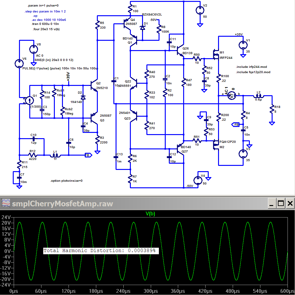
The purpose of the smplCherryMosfetAmp sim is to show that a “pure” negative feedback design can achieve the same distortion # as Bob’s feedback Error Correction circuit – which some wrongly maintain is fundamentally different from and capable of superior performance compared to high loop gain negative feedback – and this Cherry NDFL circuit sim uses fewer active devices providing forward gain
Inspecting Bob’s fig 8 front end circuit he has used 8 transistors in the VAS which function is hidden in my macromodel front in the CordellMosfetAmp sim as G2 while the smplCherryMosfetAmp sim’s circuit explicitly shows the VAS – accounting for the difference puts the smplCherry 10 transistors fewer than Bob’s EC amp
Bob’s fig 8 front end also shows a dozen “extra” parts that I interpret as being for the purpose of clamping/current limiting in saturation/clipping
So a question of fairness with respect to circuit complexity allows for ~20 more parts to add to the smplCherry circuit to control saturation/clipping behavior – or you could just put Bob’s "Klever Clipper" in front of it
An amp based on the smplCherryMosfetAmp sim circuit would in general need extra clipping/saturation recovery circuitry – a quick look at the sim’s clipping behavior shows acceptable recovery from positive clipping – which looks similar to the picture of positive clipping in Cherry’s paper, but one could suspect Cherry of being somewhat disingenuous when you look at the negative clipping recovery in the sim which does have a high frequency burst of multiple cycles – and the negative clipping recovery wasn’t shown in the Cherry paper’s ‘scope photo
Once again: high gain negative feedback can achieve similar results to Bob’s feedback Error Correction circuit – both have the same limitations – because they are fundamentally equivalent
Bob’s feedback EC circuit may have implementation advantages – but not in fundamental “desensitivity” performance; output Z reduction, distortion reduction, small signal stability gain/bandwith trade offs are all the same as for high gain negative feedback circuits
Hi jcx,
You've shown that the output THD can be reduced just as much by a NFB loop using fewer transistors. Could you post the loop gain and loop phase vs f to show the overall loop stability margin?
Thx.
You've shown that the output THD can be reduced just as much by a NFB loop using fewer transistors. Could you post the loop gain and loop phase vs f to show the overall loop stability margin?
Thx.
Re: Real World Implementations
Hi Pete,
Got out of bed on the wrong side?
which assumptions?
So what?
Maybe not this one, but apparently you have overlooked all the other effects (capacitances, Ft, gate series resistors etc.)
I've never said that. Don't put the wrong words into my mouth.
I just analyzed HEC in my way (i.e. looking at it as a special form of NFB) in order to make a fair comparison with 'ordinary' NFB topologies (like TMC).
Please, stop this nonsense and again, don't put the wrong words into my mouth.
1. I don't give a damn about that decent null, engineering null, mathematical null, practical null, virtual null, etc.
2. 'a decent null proves to me that there is enough margin'? What kind of margin?
Please Pete, stop your erroneous assumptions.
So do I.
Notice that TMC-amps has already been built for 99.9%. Under these circumstances it is overly ridiculous to demand the measurements results of a real amplifier. Besides, a real amp proves nothing. If it fails, much chance that it has been built the wrong way and if it really fails, a fraudulous person can still publish highly flattered results.
Therefore, I prefer simulations, as every body can easily verify the results.
Last but not least, I'm not gonna waist my precious time by building whatever amp just to convince some .... guys, who refuse using their brains, doing some simple math or running a sim.
Give his name and all the relevant details. Perhaps I can help him and explain why he was unsuccessful.
BTW, again this proves nothing, some people can't even build a crystal receiver.
No one says that Bob's amp is unstable. That's a ridiculous assumption.
1. This sentence doesn't make sense to me, as I'm not a native English speaker. So, what do you mean?
Anyhow, Cherry showed up with two things:
a. Nested differential feedback (NDFL)
b. Including the OPS into the Miller loop.
It's only the latter from which I derived the TMC concept.
Now you are talking about NDFL, right? (BTW, something that has nothing to do with TMC).
Let me tell you this: I have also designed and spiced a couple of NDFL amps and I'm really sorry for you to report that the latest design has also been built and that the result were reasonable in accordance with the simulations, despite my "simplistic models".
BTW, may I remind you that I am probably the first guy on this forum, who has modeled the weak inversion of MOSFETs and that my 'spicy' results match Bod's real measuring results extremely well.
Regarding "mis-use conditions", what's the problem? One can spice that as well and design counter measures to avoid nasty things like spikes, kinks and sticking. We have done just that and it works beautifully. Without a simulator it was a mission impossible to get it right.
My background? Does it really matter? But one thing I will give away: my income doesn't rely on audio, the best guarantee that I'm honest and objective.
Cheers, Edmond.
Hi Pete,
Got out of bed on the wrong side?
PB2 said:You make assumptions hoping to prove that I am wrong, please stop making assumptions about my reasoning.
which assumptions?
...... I consulted for a small group within a multi-billion dollar company on modelling bonding wire effects, lead frame effects and of course, lead and interconnect effects in high speed circuits. These circuits had edge speeds well under a nanosecond.
So what?
No I did not overlook the lead effects.
Maybe not this one, but apparently you have overlooked all the other effects (capacitances, Ft, gate series resistors etc.)
You don't recognize that 3.4 MHz bandwidth is huge margin over 20 KHz? You don't find a reduction of 43 dB to be enough?
I've never said that. Don't put the wrong words into my mouth.
I just analyzed HEC in my way (i.e. looking at it as a special form of NFB) in order to make a fair comparison with 'ordinary' NFB topologies (like TMC).
I could see where if it was 100 dB, you'd probably demand 150 or 200 dB and this is why I don't see this as reasonable discussion.
Please, stop this nonsense and again, don't put the wrong words into my mouth.
I'm not going to waste my time arguing, the fact that Bob's amp produces a decent null proves to me that there is enough margin in his real world implementation.
1. I don't give a damn about that decent null, engineering null, mathematical null, practical null, virtual null, etc.
2. 'a decent null proves to me that there is enough margin'?
What kind of margin? If you claim that there is something specifically wrong with Bob's design/prototype why don't you state it clearly.
Please Pete, stop your erroneous assumptions.
Further, and perhaps more important, Bob comes here and generously gives his time.
So do I.
Remember Bob, wrote the article in a peer reviewed journal, built and tested a prototype to prove out his design and concepts. And you refuse to build your circuits claiming that your simulations are "damn reliable".
Notice that TMC-amps has already been built for 99.9%. Under these circumstances it is overly ridiculous to demand the measurements results of a real amplifier. Besides, a real amp proves nothing. If it fails, much chance that it has been built the wrong way and if it really fails, a fraudulous person can still publish highly flattered results.
Therefore, I prefer simulations, as every body can easily verify the results.
Last but not least, I'm not gonna waist my precious time by building whatever amp just to convince some .... guys, who refuse using their brains, doing some simple math or running a sim.
Note that one person who built one of your designs found distortion well above your simulated claims.
Give his name and all the relevant details. Perhaps I can help him and explain why he was unsuccessful.
BTW, again this proves nothing, some people can't even build a crystal receiver.
Others here insist that Bob's design cannot be stable, did they miss the fact that he built and tested a prototype? It seems that their fear of positive feedback has caused them to loose their grip on reality. Behavior like this makes me find public forums such as this more entertaining than productive. It is unfortunate.
No one says that Bob's amp is unstable. That's a ridiculous assumption.
I would not call Cherry's nested feedback where he includes the OS in the Miller loop local feedback to the output stage.
1. This sentence doesn't make sense to me, as I'm not a native English speaker. So, what do you mean?
Anyhow, Cherry showed up with two things:
a. Nested differential feedback (NDFL)
b. Including the OPS into the Miller loop.
It's only the latter from which I derived the TMC concept.
I would be concerned about large signal performance under real world conditions where the output stage clips. These non-linear effects are difficult to simulate accurately. There's much more to consider in real world designs than the more simplistic models that you demand prove that you are correct. I certainly use such models, however I keep in mind that there is more to be tested through prototyping. Have you built a prototype and tested it under mis-use conditions?
Now you are talking about NDFL, right? (BTW, something that has nothing to do with TMC).
Let me tell you this: I have also designed and spiced a couple of NDFL amps and I'm really sorry for you to report that the latest design has also been built and that the result were reasonable in accordance with the simulations, despite my "simplistic models".
BTW, may I remind you that I am probably the first guy on this forum, who has modeled the weak inversion of MOSFETs and that my 'spicy' results match Bod's real measuring results extremely well.
Regarding "mis-use conditions", what's the problem? One can spice that as well and design counter measures to avoid nasty things like spikes, kinks and sticking. We have done just that and it works beautifully. Without a simulator it was a mission impossible to get it right.
I don't want to get into a back and forth with you Edmond as I think we have very different perspectives. I always wonder about a person's background when I strongly disagree just to understand them better. Do you have an engineering bio posted somewhere?
Pete B.
My background? Does it really matter? But one thing I will give away: my income doesn't rely on audio, the best guarantee that I'm honest and objective.
Cheers, Edmond.
jcx said:...........
and this Cherry NDFL circuit sim uses fewer active devices providing forward gain
Hi JCX,
I agree with you, but NDFL is NOT the same as 'including the OPS into the Miller loop'
Cheers, Edmond.
models used in CordellMosfetAmp and smplCherryMosfetAmp sims
http://www.diyaudio.com/forums/showthread.php?s=&postid=1072546&highlight=#post1072546
http://www.diyaudio.com/forums/showthread.php?postid=1324657#post1324657
attached - open with notepad to avoid linebreaks in "smarter" editors
Oops - added 2n5501 some people may need to reload
http://www.diyaudio.com/forums/showthread.php?s=&postid=1072546&highlight=#post1072546
http://www.diyaudio.com/forums/showthread.php?postid=1324657#post1324657
attached - open with notepad to avoid linebreaks in "smarter" editors
Oops - added 2n5501 some people may need to reload
Attachments
- Home
- Amplifiers
- Solid State
- Bob Cordell Interview: Error Correction