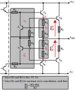
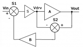
Given the former, further insight in the remarkable linearity of Hawksford/Cordell may be gained by comparing the basic block diagram with the nominal practical implementation given below.
Clearly the linearity of summer S1 is beyond reproach since it consists entirely of resistors! 🙂
Summer S2, on the other hand, consists of an active element, T1, and two resistors, R1 and R2.
The presence of T1 may at first appear dubious in respect of linearity, but this notion is quickly dispelled by the realisation that its non-linearity is significantly ameliorated by the heavy local feedback provided by emitter degenerative resistor R2. Indeed, in Bob's circuit this transistor is only required to generate a nominal gain of 2.
To my mind, the foregoing explains the remarkable practical performance obtained by Bob's circuit.
Nevertheless, it may be taken as axiomatic that residual summer non-linearity in the correction loop is entirely due to transistor T1.
This, of course, also applies to the negative polarity arrangement of transistor T2.
Attachments
janneman said:.....the loop is still there, but it's input (and output) is zero. There is no feedback so talking about its gain for a non-existing signal is meaningless.
In a 'regular' feedback loop there always is a signal and always feedback, so even with a perfectly linear and defined gain block you have feedback.
Jan
That is exactly my point! 100% correct-Thank you!

Bob wrote:
🙂 Earlier in this thread you were saying how great it was to be able to tune the distortion to a minimum. I agree with what you say...once you've tuned it you can replce the pot with a precision resistor. The tuning is necessary in the first place because the PFB is so sensitive to resistor values. I can't see why you would choose to have this step *if* you were able to use an integrator in the circuit.Bear in mind that my circuit does not "need" an adjustment. Implementation with fixed precision resistors will do just fine. Moreover, the "adjustment" mostly affects fine tuning of the cancellation at lower frequencies where it is not that important.
mikeks said:
You're pulling my leg, right?
I am deadly serious Michael, please review.
If someone else here coincides that in a linear (constant or at most frequency dependent coeficients) representation of a system where errors / disturbances are introduced as external perturbations, system gain is possibly dependent on the magnitude of this perturbations, then please share.
Rodolfo
powerbecker said:
......
BTW, can you explain the way to export the error-log??
Heinz!
The old paint-copy-paste trick, but I suspect the actual log file (plain text) is also dumped on disk, did not check.
Rodolfo
ingrast said:
....please review.
Rodolfo
Hi Rodolfo,
Perhaps this is yet another case of misunderstanding.
I have reviewed your figure 3 below extracted from here, with 1/A' set to unity.
Now, noting that S must be unity at balance, what is S2's output when A is exactly unity?
Otherwise, what happens to your major-loop gain when A is exactly unity?
Attachments
Bob wrote:
I share Nixie's experiences. There have been many "low THD" designs on the market that have not satisfied sonically and vice versa. I have followed a process of measure, listen, improve the measure, improve the circuit, listen, improve the measure... This process has taught me that basic THD is only half the story.THD-20 is a very good test, but it is not a complete test, for shure. I usually prefer 19 + 20 kHz twin tone with full spectral analysis for high frequency non linearity. And, of course, there is no substitute for a decent listening test.
That having been said, please elaborate on your experience with THD not having been a reliable measure of accuracy.
mikeks said:
Hi Rodolfo,
Perhaps this is yet another case of misunderstanding.
I have reviewed your figure 3 below extracted from here, with 1/A' set to unity.
Now, what is S2's output when A is exactly unity?
Otherwise, what happens to your major-loop gain when A is exactly unity?
I bet it is misunderstanding.
By the very nature of the error correction approach, output of S2 when A=A' (which is the same to say unity gain plant and bypass of 1/A') is null. This is only to be expected and lends to Jan's insight, no error ->no feedback. It mus be understood the fact there is no error signal does not mean at all there is no gain or whatever.
What brings confussion to this simplified approach is the fact the inner loop embodies in fact a singularity, making simplified calculations including balance from the outset to fall appart.
I was from the start cautious to not include directly the cancellation condition, for doing so is what brings chaos. Further, recognizing at least one element in the inner loop chain must be active (I considered natural S(s)) the singularity automatically disappears except for s=0.
An please, it was you who was pulling my leg with the dimensions issue, weren't you?
Rodolfo
traderbam said:Bob wrote: 🙂 Earlier in this thread you were saying how great it was to be able to tune the distortion to a minimum. I agree with what you say...once you've tuned it you can replce the pot with a precision resistor. The tuning is necessary in the first place because the PFB is so sensitive to resistor values. I can't see why you would choose to have this step *if* you were able to use an integrator in the circuit.
Brain, Mike,
In practise, the 'gain' of the ec transistors in Bob's circuit is actually Ic/Ie multiplied by the resistor ratio mentioned by Mike. Since Ic/Ie is probably much less deviation from '1' than 1%, using 1% resistors effectively make the (non)linearity of the transistors a secondary effect. Especially when they are biased at a DC current which probably is larger than any practical error current variations: they work in class A. No?
Jan Didden
janneman said:
In practise, the 'gain' of the ec transistors in Bob's circuit is actually Ic/Ie multiplied by the resistor values.
Jan Didden
Not really. See:
http://www.diyaudio.com/forums/showthread.php?postid=1071612#post1071612
and
http://www.diyaudio.com/forums/showthread.php?postid=1073471#post1073471
lumanauw said:Hi, Bob,
In your paper your amp doesn't use output inductor (//R?)
What is the proper output inductor looks like for your amp as in your paper? (how many turns, diameter, wire diameter, how many ohm of the //Resistor)
It was on the order of 1 uH, 1-ohm in parallel. Its not very critical.
Bob
traderbam said:Bob wrote: 🙂 Earlier in this thread you were saying how great it was to be able to tune the distortion to a minimum. I agree with what you say...once you've tuned it you can replce the pot with a precision resistor. The tuning is necessary in the first place because the PFB is so sensitive to resistor values. I can't see why you would choose to have this step *if* you were able to use an integrator in the circuit.
Brian, it's just so much fun to tune the circuit and watch the error go through zero!
Cheers,
Bob
Bob Cordell said:
Brian, it's just so much fun to tune the circuit and watch the error go through zero!
Cheers,
Bob
Of interest, Bob, over what bandwidth does this effect extend in your design?
The effect itself is perhaps not surprising considering the high linearity of the loop.
ingrast said:
I am deadly serious Michael, please review.
If someone else here coincides that in a linear (constant or at most frequency dependent coeficients) representation of a system where errors / disturbances are introduced as external perturbations, system gain is possibly dependent on the magnitude of this perturbations, then please share.
Rodolfo
The small-signal gains within the EC loop(s) are largely independent of the amplitude of the errors, as long as clipping is not approached. Rodolfo is correct.
Bob
Bob Cordell said:
The small-signal gains within the EC loop(s) are largely independent of the amplitude of the errors, as long as clipping is not approached. Rodolfo is correct.
Bob
Some misunderstanding here.
The individual ''small-signal gains within the EC loop(s)'' are certainly ''largely independent of the amplitude of the errors, as long as clipping is not approached'', as i have pointed out here.
However, this was not the issue referred to by Rodolfo and i, here, here and here.
Clearly the matter was about the major loop, and not individual ''small-signal gains''.
On this basis, therefore, i fail to see how Rodolfo could possibly be correct.
powerbecker said:Nix "error-correction": 😉
To throw some numbers at that moment from my latest simulation with (a lot of) common NFB:
50W 8E max, 20kHz 36W/8E : 0.000022%, bandwidth DC-500kHz, gain 24dB, PSR 100 (!) kHz - 135dB.
I use Andy´s fets.
Who bid better 😀
Regards
Heinz! 😎
I change some parts: THD20 is now 0.000006%
Yes, I know...it´s only a simulation...
The amp is so simple that it fits to the NP-forum, but I´m afraid not for the sound 😉
Heinz!
Attachments
powerbecker said:
Hello Tom ,
I tried your circuit and it works good!
You are a "precisions-fan"! 🙂 Because I´m too lazy I do my sims normally without so much details.
I make a 2. circuit, where I use inverting mode. Often I prefer this, because I had not to consider CMR of the Opamps. (both : in reality and in the models)
Beside this the circuit get smaller now also the result is a bit better: 0.000237%. The Opa541 alone with a gain 20 bring 0.0084%!
As for me usual I test the behavior only with sinus/rectangle.....
Jan, Rudolfo,
it will be interesting for me to get some measurements from your amps, please post them.
Regards
Heinz!
Thank you, Heinz!
I like your circuit, very much.
I added a notch filter to my original circuit's ec loop, and was then able to increase the gain enough to get .000119% THD-20. But, also, the step response is still very good (after carefully configuring the filter). The new circuit should be attached. Otherwise, it should be able to be downloaded from http://www.fullnet.com/~tomg/ec_amp-tg2.asc.txt .
I would like to try to convert it into a similar topology as yours, but still keep the good step response.
Sorry about all of the parasitic capacitors, et al. It's just a habit, now.
Thanks again.
- Tom Gootee
Attachments
- Home
- Amplifiers
- Solid State
- Bob Cordell Interview: Error Correction