"Hey, you asked for it"
All I asked for is an improved circuit. I think this is more accurately described as harrassment. Since I'm a very nice guy and your resident shiny example
  , here goes:
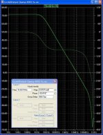
f=1kHz, Vout=1Vrms
resistors disconnected:
k2=0.188
k3=0.011
resistors connected:
k2=0.009
k3=0.005
f=20kHz, Vout=1Vrms
resistors disconnected:
k2=0.03
k3=0.003
resistors connected:
k2=0.002
k3=0.004
Max. resolution of the Analyzer is 0.001%.
Load: a real world loudspeaker (a beautiful real world loudspeaker! with Heils!)
Regards,
Milan
P.S. Re R42 & 43, thanks for the tip but that much I kinda knew already.
All I asked for is an improved circuit. I think this is more accurately described as harrassment.
Since I'm a very nice guy and your resident shiny example , here goes:f=1kHz, Vout=1Vrms
resistors disconnected:
k2=0.188
k3=0.011
resistors connected:
k2=0.009
k3=0.005
f=20kHz, Vout=1Vrms
resistors disconnected:
k2=0.03
k3=0.003
resistors connected:
k2=0.002
k3=0.004
Max. resolution of the Analyzer is 0.001%.
Load: a real world loudspeaker (a beautiful real world loudspeaker! with Heils!)
Regards,
Milan
P.S. Re R42 & 43, thanks for the tip but that much I kinda knew already.
thanh said:@gootee: I downloaded your schematic, file .asc 17KB. I open it by LTSpice but there is nothing
Thanh,
Sorry. Let me try again:
http://www.fullnet.com/~tomg/EC_Amp.asc.txt , which needs to be saved with only a .asc filename-extension, and
http://www.fullnet.com/~tomg/opa541e.sub.txt , which needs to be saved with only a .sub filename-extension.
- Tom Gootee
Milan, you are a very nice guy. 
I assume those results are fractions of the fundamental. I thought before you said K2 and K3 at 20kHz were 0.0005?
Anyhow, the K2 ratios show 26dB improvement at 1kHz and 24dB at 20kHz with EC feedback. Not too shabby! 🙂
The K3 ratios are much smaller; could this be measurement accuracy? It is weird that K3 increases at 20KHz with EC applied.
The most interesting result is that K2 is over 13dB smaller at 20kHz than at 1kHz. Can you explain this?
Brian
Expect more harrassment soon...no pain, no gain.
powerbecker said:This is not the amp I mention before!
Very clever, Heinz! This looks like something Brian might be interested in (uses feedback, no trimmer).
gootee said:
Thanh,
Sorry. Let me try again:
http://www.fullnet.com/~tomg/EC_Amp.asc.txt , which needs to be saved with only a .asc filename-extension, and
http://www.fullnet.com/~tomg/opa541e.sub.txt , which needs to be saved with only a .sub filename-extension.
- Tom Gootee
Tom,
I try your EC-Amp, but it seems, that the opa541 model don´t work : the output is limited to +/- 200 mV ??!
Any suggestions?
Andy, thank you!
Heinz!
traderbam said:Anyhow, the K2 ratios show 26dB improvement at 1kHz and 24dB at 20kHz with EC feedback. Not too shabby! 🙂
The K3 ratios are much smaller; could this be measurement accuracy? It is weird that K3 increases at 20KHz with EC applied.
The most interesting result is that K2 is over 13dB smaller at 20kHz than at 1kHz. Can you explain this?
At 1kHz I don't think that the K3 ratios have much to do with measurement accuracy. On the other hand, it's almost certain that the K3 measurements at 20kHz are not exceptionally accurate.
The difference between K2 at 1kHz and 20kHz may be partly due to measurement inaccuracies at 20kHz (as with K3) but also due to the real world speakers that were used. Finally, I didn't use proper measuring cables but those that happened to be at hand at the moment.
Also, there is a distinct possibility that this is not NFB we're discussing here.

As for harrassment, pain and gain, you really must be looking forward to mikeks's upcoming discharge from the SinBin.

Regards,
Milan
Focussing on the output stage, here's the output stage feedback loop gain with the input grounded. Unity gain at 15MHz - very fast. I noticed you've bootstrapped the output driver psu to the output. Lots of things to look at from both distortion and stability perspectives.This is not the amp I mention before!
Attachments
Hey, Milan, you are a nice guy and a troublemaker.
I forgot you were doing these measurement with a speaker. That's a terrible load for an amp, how inappropriate - go back and repeat the test with an 8 ohm resistor.
Only if you feel like it I think the result is meaningful anyhow. For future simulator comparisons it'll have to be a simple load like a resistor or a capacitor
I forgot you were doing these measurement with a speaker. That's a terrible load for an amp, how inappropriate
- go back and repeat the test with an 8 ohm resistor. Only if you feel like it
I think the result is meaningful anyhow. For future simulator comparisons it'll have to be a simple load like a resistor or a capacitor traderbam said:I forgot you were doing these measurement with a speaker.
Hmmm, and this was only 6 posts earlier... I think a nice bath, some cookies and a glass of milk might do you much more good at this hour than any of my measurements.
Good night,
Milan
traderbam said:Focussing on the output stage, here's the output stage feedback loop gain with the input grounded. Unity gain at 15MHz - very fast. I noticed you've bootstrapped the output driver psu to the output. Lots of things to look at from both distortion and stability perspectives.
Brian,
output driver PSU is (and must!) be bootstrapped to the input of the powerstage.
This I use frequently more then 20 years, only the last 10years I do it also in simulations.....because I started with computer and simulations late in 1996 😉
Therefor I use for stability tests normally rectangle signals...on the bench it´s hard to measure the (open) loop gain!
Heinz!
The beauty of this circuit is that when the loop gain of the error correction loop goes to zero, the feedback just "gets out of the way", allowing the circuit to have its natural bandwidth. It's my view that Heinz has just cracked the problem of error correction without adjustment.
powerbecker said:
Tom,
I try your EC-Amp, but it seems, that the opa541 model don´t work : the output is limited to +/- 200 mV ??!
Any suggestions?
Heinz!
Heinz,
I have tried it only with LT-Spice, from linear.com . Is that what you are using?
Also, LT-Spice's "Alternate Solver" should be used (but mainly for better sim speed, here).
And, I don't know if it should matter, but, I have LT-Spice version 2.18A.
I just now downloaded the same files and it works OK, here, giving a 20V p-p "sine" output, as downloaded. Then, disconnecting the sine source and connecting the pulse source, I got 20 v p-p "squarewave" out.
Note that during or after downloading, the op541e.sub.txt file must be renamed to be opa541e.sub .
In case you want to verify that the opa541 model file has not changed, I found the OPA541 model by using this site:
http://homepages.which.net/~paul.hills/Circuits/Spice/ModelIndex.html
which eventually led me to this page:
http://focus.ti.com/analog/docs/gencontent.tsp?familyId=2&genContentId=884
Then, after downloading http://focus.ti.com/packaged_lits/spice_files/ti_spice_models.zip and http://focus.ti.com/packaged_lits/spice_files/ti_spice_models_index.txt , I used WINZIP and extracted the file named SBOM085.ZIP, which contains the OPA541E.MOD file, which I then renamed to have a .SUB filename-extension.
Also note that, in the ec_amp.asc circuit, the gain of the opa541 is set to 20. A gain of 20 is optimal for the LM3875 (which I wanted to use but couldn't find a model for it). But I have read that a gain of 10 is probably better for the opa541.
- Tom Gootee
gootee said:
Heinz,
I have tried it only with LT-Spice, from linear.com . Is that what you are using?
Also, LT-Spice's "Alternate Solver" should be used (but mainly for better sim speed, here).
And, I don't know if it should matter, but, I have LT-Spice version 2.18A.
I just now downloaded the same files and it works OK, here, giving a 20V p-p "sine" output, as downloaded. Then, disconnecting the sine source and connecting the pulse source, I got 20 v p-p "squarewave" out.
Note that during or after downloading, the op541e.sub.txt file must be renamed to be opa541e.sub .
In case you want to verify that the opa541 model file has not changed, I found the OPA541 model by using this site:
http://homepages.which.net/~paul.hills/Circuits/Spice/ModelIndex.html
which eventually led me to this page:
http://focus.ti.com/analog/docs/gencontent.tsp?familyId=2&genContentId=884
Then, after downloading http://focus.ti.com/packaged_lits/spice_files/ti_spice_models.zip and http://focus.ti.com/packaged_lits/spice_files/ti_spice_models_index.txt , I used WINZIP and extracted the file named SBOM085.ZIP, which contains the OPA541E.MOD file, which I then renamed to have a .SUB filename-extension.
Also note that, in the ec_amp.asc circuit, the gain of the opa541 is set to 20. A gain of 20 is optimal for the LM3875 (which I wanted to use but couldn't find a model for it). But I have read that a gain of 10 is probably better for the opa541.
- Tom Gootee
Thank you Tom, now it works, my mistake : I use the "universalopamp2" instead the "opamp2"
It´s too late for a closer look to your circuit , my bed calls me!Heinz!
You're making the same error as the listener preferences people are in that you think your measure is the correct one to use. Neither is. The correct measure is a blind test to determine if a specific distortion is perceivable. The classic way of doing this is given a set between which the listeners can switch, whether the listeners can pick out the reference in a set of trials with statistical significance. Note that nowhere in this does 'preference' play a part!janneman said:in this thread we discuss design linearity issues, not listener preferences.
It makes no sense to design for, say minimum THD, since it's well known that some forms of THD are inaudible in very large amounts, whereas others, not to mention other types of distortion, are audible in tiny amounts. Minimizing a non-perceptually correlated metric forces you to try to reach for extremely low thresholds for all types of distortion, whereas in practice it's only necessary to make sure each is below its perceptible threshold. For example, 2nd order THD and smooth, continuous phase distortion are not audible even if present in significant amounts. So expending as much effort on minimizing such as on other types of distortion is silly. It makes sense to design for a metric that is weighted to correlate with perceptibility.
Nixie,
What you say is true but I have problems based on it's practical importance. I have listened to demonstrations showing how relatively high levels oh 2nd order distortion are in audible while very small amounts of certain high order distortions are very obvious and obnoxious. The problem with the demos is that the obnoxious high order distortions are far worse than anything I've ever heard even in the cheapest most crude amplifiers such as in $20 powered PC speakers.
Further, although I've not looked at the FFT spectrums of as many different (SS) amplifiers as some members here, I've checked out enough that I have the strong impression that across a pretty wide spectrum of models it is the norm that the amount of distortion drops off pretty rapidly with higher orders. The only cases where I've seen evidence of noteworthy amounts of high order harmonics (assuming clipping is not approached, etc) is when something was defective, my own screw up or a soft-clip circuit was in operation.
So while the point is well taken that simply looking for low THD doesn't do much, the spectre of an amplifier design with impressive THD figures but dreadful sonics due to high order harmonics doesn't seem like something to be too worried about.
By the way the demos described in the first paragraph were constructed digitally with an editor such as Goldwave or a similar product. The "bad distortion" was so bad that I doubt it can be found in real-life even at a much lower level.
I would be interested if someone has a real life example of a commercial amplifier currently in production that exhibits a serious problem in this regard. (If there is one I'll bet it's some horribly expensive high-end job.)
sam9, I didn't want to concentrate on THD, as it's just one type of distortion, and seems to be the least important in light of the paper I mentioned previously. Phase intermodulation, thermal/memory distortion, speaker interactions, jitter getting in the D/A if you include that part of the chain, etc., seem to be far more significant in terms of perceptibility. Some of these are rarely measured and likely play a part in why two amplifiers both of which have THD and IMD below established thresholds of perceptibility can sometimes still be distinguished in blind tests.
In addition, let's not forget that perceptibility thresholds are established by using real equipment, so one cannot be sure that some effects may not be detected because they are simply masked by other distortions in the system.
In addition, let's not forget that perceptibility thresholds are established by using real equipment, so one cannot be sure that some effects may not be detected because they are simply masked by other distortions in the system.
Nixie said:
You're making the same error as the listener preferences people are in that you think your measure is the correct one to use. Neither is. The correct measure is a blind test to determine if a specific distortion is perceivable. The classic way of doing this is given a set between which the listeners can switch, whether the listeners can pick out the reference in a set of trials with statistical significance. Note that nowhere in this does 'preference' play a part!
It makes no sense to design for, say minimum THD, since it's well known that some forms of THD are inaudible in very large amounts, whereas others, not to mention other types of distortion, are audible in tiny amounts. Minimizing a non-perceptually correlated metric forces you to try to reach for extremely low thresholds for all types of distortion, whereas in practice it's only necessary to make sure each is below its perceptible threshold. For example, 2nd order THD and smooth, continuous phase distortion are not audible even if present in significant amounts. So expending as much effort on minimizing such as on other types of distortion is silly. It makes sense to design for a metric that is weighted to correlate with perceptibility.
Nixie,
I think you're barking up the wrong tree. When I said that we discuss linearity in this thread, not listener preference, that was just a factual statement. And when I said that listener preference is not a good measure of amp linearity, that was just a factual statement.
For all the rest, I fully agree with your view that controlled, (double) blind tests with enough statistically valid trials are the only reliable tests to find out whether two pieces of equipment sound different. Which STILL doesn't tell you which one is more linear, of course.
Jan Didden
janneman said:
For all the rest, I fully agree with your view that controlled, (double) blind tests with enough statistically valid trials are the only reliable tests to find out whether two pieces of equipment sound different. Which STILL doesn't tell you which one is more linear, of course.
Hmmm.... I can tell by my listening/experimenting experience what kind of distortions present when "blind tests" of listeners reveal that "something is wrong with the sound". And I totally agree with Nixie about what kind of distortions to minimize means more than how to minimize some distortions that no need to minimize on the background of more audible and less pleasant distortions. And again, I speak of the same tendention, when you tend to shift crossover distortions close and close to zero power assuming that it makes them less audible because of less measurable, that is the mistake.
Let me ask this then: how do you define a degree of linearity? If given full details of the distortion of an amplifier, how would you calculate a number specifying the linearity?janneman said:Which STILL doesn't tell you which one is more linear, of course.
- Home
- Amplifiers
- Solid State
- Bob Cordell Interview: Error Correction