Nixie said:
Let me ask this then: how do you define a degree of linearity? If given full details of the distortion of an amplifier, how would you calculate a number specifying the linearity?
I don't
I don't know.
Now can we get back on topic please?
Jan Didden
But that is a topic you brought up:Originally posted by janneman
Now can we get back on topic please?
If you can't define it, how can you compare?Which STILL doesn't tell you which one is more linear, of course.
Nixie said:
But that is a topic you brought up:
If you can't define it, how can you compare?
Hey, let it go! I was reacting to a Traderbam post. You missed the whole discussion and now start pick and chose bits and pieces.
You'll be on your own on this from here on. Sorry.
Jan Didden
Heinz wrote:
Andy wrote:
I was looking at PFB distortion vs integrator distortion last night. I made two spice models, each using two BJTs. The PFB was like Bob's darlington. The integrator was made using a capacitor, NFB loop. The BJTs were run at identical bias currents, I made the frequency responses as close as I could, etc. I found in the PFB the distortion of the BJTs was amplified, the output Z was increased and the input Z increased. The opposite with the NFB integrator. Consider that the circuit is being fed from a fairly low Z and is driving non-linear FET input Z.
Did you see my questions about those Spice models, Andy?
Yes, I see that. My mistake. I had the Halcro design on my mind last night. I must get a life. 😀output driver PSU is (and must!) be bootstrapped to the input of the powerstage.
Andy wrote:
Yes, this is one way to do it. An integrator in place of the PFB loop doesn't need the adjustment.It's my view that Heinz has just cracked the problem of error correction without adjustment.
I was looking at PFB distortion vs integrator distortion last night. I made two spice models, each using two BJTs. The PFB was like Bob's darlington. The integrator was made using a capacitor, NFB loop. The BJTs were run at identical bias currents, I made the frequency responses as close as I could, etc. I found in the PFB the distortion of the BJTs was amplified, the output Z was increased and the input Z increased. The opposite with the NFB integrator. Consider that the circuit is being fed from a fairly low Z and is driving non-linear FET input Z.
Did you see my questions about those Spice models, Andy?
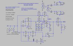
gootee said:
Also note that, in the ec_amp.asc circuit, the gain of the opa541 is set to 20. A gain of 20 is optimal for the LM3875 (which I wanted to use but couldn't find a model for it). But I have read that a gain of 10 is probably better for the opa541.
- Tom Gootee
Hello Tom ,
I tried your circuit and it works good!
You are a "precisions-fan"! 🙂 Because I´m too lazy I do my sims normally without so much details.
I make a 2. circuit, where I use inverting mode. Often I prefer this, because I had not to consider CMR of the Opamps. (both : in reality and in the models)
Beside this the circuit get smaller now also the result is a bit better: 0.000237%. The Opa541 alone with a gain 20 bring 0.0084%!
As for me usual I test the behavior only with sinus/rectangle.....
Jan, Rudolfo,
it will be interesting for me to get some measurements from your amps, please post them.
Regards
Heinz!
Attachments
Nixie said:
You're making the same error as the listener preferences people are in that you think your measure is the correct one to use. Neither is. The correct measure is a blind test to determine if a specific distortion is perceivable. The classic way of doing this is given a set between which the listeners can switch, whether the listeners can pick out the reference in a set of trials with statistical significance. Note that nowhere in this does 'preference' play a part!
It makes no sense to design for, say minimum THD, since it's well known that some forms of THD are inaudible in very large amounts, whereas others, not to mention other types of distortion, are audible in tiny amounts. Minimizing a non-perceptually correlated metric forces you to try to reach for extremely low thresholds for all types of distortion, whereas in practice it's only necessary to make sure each is below its perceptible threshold. For example, 2nd order THD and smooth, continuous phase distortion are not audible even if present in significant amounts. So expending as much effort on minimizing such as on other types of distortion is silly. It makes sense to design for a metric that is weighted to correlate with perceptibility.
You're not entirely correct, and you're not entirely wrong. First of all, matters of perceptibility, subjective evaluation and blind listening tests are extremely important and interesting, but they should not play a significant role in this thread. They should be in another thread. This thread is for examining error correction techniques and alternative topologies, with objective basis for comparison of results. It largely amounts to evaluation of achieved linearity in the different approaches. THD-20 is actually quite good in that role, and is widely available both in meaurement and simulation. Spectral analysis is also desirable.
It is true that there are probably some odd types of distortion that escape these type of static tests, such as thermal, etc, but they will be equally important for non-EC amplifiers.
Crossover distortion is one of the most insidiuous forms of distortion, and it generally does not escape detection by THD-20. Much of what EC does is to attack crossover distortion, so this argues for the relevance of THD-20 in this thread.
Don't confuse THD-20 with THD-1. THD-1 is MUCH less useful than THD-20, since the huge NFB factors at lower frequencies that some amplifiers use can drive THD-1 almost into oblivion while there remain serious crossover and other HF distortions.
Just because THD-20 is not perfect and not complete, don't throw the baby out with the bathwater.
Bob
sam9 said:Nixie,
I would be interested if someone has a real life example of a commercial amplifier currently in production that exhibits a serious problem in this regard. (If there is one I'll bet it's some horribly expensive high-end job.)
I love it! 🙂
Bob
Hi, Bob,
If today you are about to design EC, will it the same as your Mosfet EC or it will be different schematic (for the same purpose = EC)?
If today you are about to design EC, will it the same as your Mosfet EC or it will be different schematic (for the same purpose = EC)?
powerbecker said:
.......
Jan, Rudolfo,
it will be interesting for me to get some measurements from your amps, please post them.
Regards
Heinz!
Atached is LTSpice error log snip just extracted. Note of caution, while simulations are fantastic tools for quickly evaluating scenarios, I do not put my money on results like -150 dB relative spurious levels as computed.
This is because both device modeling has been shown to be of variable accuracy, and of course because actual subtle effects in component departure from ideal (resistors, capacitors) and wiring / layout are not included.
Measurements on actual hardware, proven by at least several hours or preferably more of punishment and actual listening are much more close to what we want to know about a certain design.
Rodolfo
PD I posted actual measurements earlier in this thread, I can repeat if you have trouble finding it.
Attachments
Nixie said:sam9, I didn't want to concentrate on THD, as it's just one type of distortion, and seems to be the least important in light of the paper I mentioned previously. Phase intermodulation, thermal/memory distortion, speaker interactions, jitter getting in the D/A if you include that part of the chain, etc., seem to be far more significant in terms of perceptibility. Some of these are rarely measured and likely play a part in why two amplifiers both of which have THD and IMD below established thresholds of perceptibility can sometimes still be distinguished in blind tests.
In addition, let's not forget that perceptibility thresholds are established by using real equipment, so one cannot be sure that some effects may not be detected because they are simply masked by other distortions in the system.
Phase Intermodulation Distortion was discussed and put to rest way earlier in this thread. I've measured it; very few other people have, as it requires special instrumentation. It is not generally a problem. It is virtually impossible for it to show up in an amplifier without that same amplifier also exhibiting substantial amounts of THD-20. Finally, total PIM is not exacerbated by negative feedback, as some have asserted. Actual measurements usually show that the application of negative feedback reduces total PIM. This is because there is PIM in the total absence of NFB (commonly known as differential phase in the video community) that is normally larger than that which is theoretically created by NFB. Much misinformation has circulated on this subject. See my paper on PIM on my website at www.cordellaudio.com.
The papers you cited on thermal distortions appear to be extremely interesting, and I hope to read them in detail and sort it all out. I am interested in hearing what others in this thread think about those papers.
Bob
traderbam said:Heinz wrote:Yes, I see that. My mistake. I had the Halcro design on my mind last night. I must get a life. 😀
Andy wrote:Yes, this is one way to do it. An integrator in place of the PFB loop doesn't need the adjustment.
I was looking at PFB distortion vs integrator distortion last night. I made two spice models, each using two BJTs. The PFB was like Bob's darlington. The integrator was made using a capacitor, NFB loop. The BJTs were run at identical bias currents, I made the frequency responses as close as I could, etc. I found in the PFB the distortion of the BJTs was amplified, the output Z was increased and the input Z increased. The opposite with the NFB integrator. Consider that the circuit is being fed from a fairly low Z and is driving non-linear FET input Z.
Did you see my questions about those Spice models, Andy?
Bear in mind that my circuit does not "need" an adjustment. Implementation with fixed precision resistors will do just fine. Moreover, the "adjustment" mostly affects fine tuning of the cancellation at lower frequencies where it is not that important. Amount of EC improvement at high frequencies, like THD-20, actually tends more to be limited by circuit speed and need for compensation that it is by small innacuracies in the static component values.
Bob
lumanauw said:Hi, Bob,
If today you are about to design EC, will it the same as your Mosfet EC or it will be different schematic (for the same purpose = EC)?
Essentailly the same topology, but some subtle refinements.
Bob
Hi, Bob,
In your paper your amp doesn't use output inductor (//R?)
What is the proper output inductor looks like for your amp as in your paper? (how many turns, diameter, wire diameter, how many ohm of the //Resistor)
In your paper your amp doesn't use output inductor (//R?)
What is the proper output inductor looks like for your amp as in your paper? (how many turns, diameter, wire diameter, how many ohm of the //Resistor)
ingrast said:Well Michael, let's see.
The first link points to an equation where for example there are factors of the form K+e. This is dimensionally incorrect for it implies sum of a dimensionless term (K) and a voltage/current or whatever physical magnitude.
You're pulling my leg, right?

Where are your ''correct'' dimensions here?
Voltage gain, as exemplified by block diagrams, has no units.
Actually, K is a function of ''s'', but, like you, i thought that was obvious and incidental to the proof given here.
The point is the system's major loop, if balanced, cannot generate any loop-gain (if the output stage possess exactly unity gain).
Something Jan referred to as ''feedback-on-demand''.
ingrast said:The second link points to a gain expression coincident with mine, where the error term does not appear as a variable affecting the result.
Rodolfo
The tenuous inclusion of the (1/A') block constitutes the fatal flaw in your your analysis.
This is because its presence in your closed-loop transfer function, G, (equation 2) needlessly provides the condition for positive feedback in the major loop.
Viz. |1/A'|<|1/A|
Which nicely proves my point: there is no such thing as ''infinite'' loop-gain in the major loop at balance.
ingrast said:.....the presence of error or lack of it does not affect system gain.
Rodolfo
This is manifestly, egregiously and atrociously incorrect, for the ''error'' at issue is that produced by the voltage follower output stage. Were this error reduced to zero by using an ideal output stage, then you could not logically have gain within the major loop, as summer S1 here would produce zero output.
Folks, please take note: this is priceless information. 
Bob Cordell said:
Bear in mind that my circuit does not "need" an adjustment. Implementation with fixed precision resistors will do just fine. Moreover, the "adjustment" mostly affects fine tuning of the cancellation at lower frequencies where it is not that important. Amount of EC improvement at high frequencies, like THD-20, actually tends more to be limited by circuit speed and need for compensation that it is by small inaccuracies in the static component values.
Bob

mikeks said:[snip]the ''error'' at issue is that produced by the voltage follower output stage. Were this error reduced to zero by using an ideal output stage, then you could not logically have gain within the major loop[snip]
Mike,
I agree with this analysis. But probably it is also a semantic or interpretation issue: the loop is still there, but it's input (and output) is zero. There is no feedback so talking about its gain for a non-existing signal is meaningless.
In a 'regular' feedback loop there always is a signal and always feedback, so even with a perfectly linear and defined gain block you have feedback. But why should I repeat myself again?
Jan
ingrast said:
Atached is LTSpice error log snip just extracted. Note of caution, while simulations are fantastic tools for quickly evaluating scenarios, I do not put my money on results like -150 dB relative spurious levels as computed.
This is because both device modeling has been shown to be of variable accuracy, and of course because actual subtle effects in component departure from ideal (resistors, capacitors) and wiring / layout are not included.
Measurements on actual hardware, proven by at least several hours or preferably more of punishment and actual listening are much more close to what we want to know about a certain design.
Rodolfo
PD I posted actual measurements earlier in this thread, I can repeat if you have trouble finding it.
Rudolfo, thank you,
that is formidable!!
When I test also with 10 harmonics I get exact the same number, with 15harm. I read 0.000022%.
For fun I´ll try to get down 😀
BTW, can you explain the way to export the error-log??
Heinz!
- Home
- Amplifiers
- Solid State
- Bob Cordell Interview: Error Correction