

Of course I was no longer able to achieve the goal of no ringing with square waves into a 2uF load. I've reached the conclusion that such a goal is a "fool's errand". Chalk that one up to inexperience.
I wonder why people always test with stability towards 2uF capacitor? Where does this test coming from?
This is a setup procedure for professional amp. It only uses 0.47uF max and still allows ringing.
Attachments
lumanauw said:I wonder why people always test with stability towards 2uF capacitor? Where does this test coming from?
I think this comes from the original Quad electrostatic speakers from long ago. They supposedly looked like 2uF. I don't know if this is actually true though.
When there is an output inductor, the ringing in that test is not from instability, but from the L and C creating an underdamped passive circuit.
Hi, AndyC,
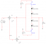
What is your opinion on Etalon schematic on post #985? It doesn't use R1, so it doesn't fit into Hawksford's equation.
Is it EC around it's VBE multiplier or not?
What is your opinion on Etalon schematic on post #985? It doesn't use R1, so it doesn't fit into Hawksford's equation.
Is it EC around it's VBE multiplier or not?
lumanauw said:how come in this schematic, the EC don't have R1?
Is this means this Etalon schematic is not using EC?
That's a wild looking circuit! I can't say I understand exactly how it works, but it appears like there's some kind of EC happening via current summing at the bases of the predrivers (third transistors from the right).
Bad Mike!
Block diagram summers can easily be implemented in any spice with Voltage Dependant Voltage Sources
It can however be a really bad idea
It is easy to create this "infinite gain" situation that is completely non-physical
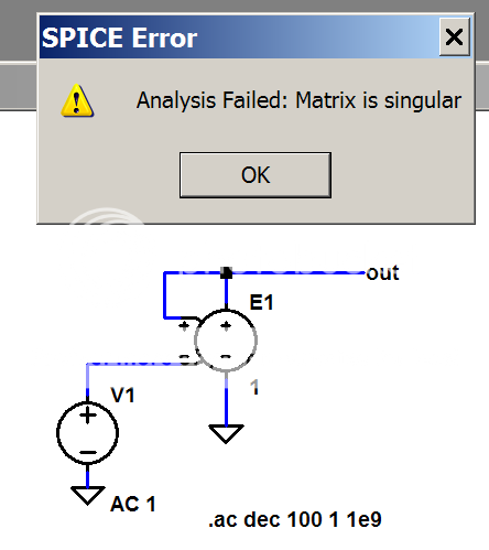
(try changing E1 gain to 0.999999 or 1.000001, then you get -/+ 1e6 Av with flat phase shift)
This is a big move backwards in trying to understand the real circuit's properties
All such summers must be implemented with real, causual transfer functions that have high frequency roll off and phase shift to avoid completely unreal gains from positive feedbacks
gains which are hidden by the innocuous seeming gain 1 block (“watch the fingers folks, see nothing up my sleeves… just these little unity gain summers…”)
Block diagram summers can easily be implemented in any spice with Voltage Dependant Voltage Sources
It can however be a really bad idea
It is easy to create this "infinite gain" situation that is completely non-physical
(try changing E1 gain to 0.999999 or 1.000001, then you get -/+ 1e6 Av with flat phase shift)
This is a big move backwards in trying to understand the real circuit's properties
All such summers must be implemented with real, causual transfer functions that have high frequency roll off and phase shift to avoid completely unreal gains from positive feedbacks
gains which are hidden by the innocuous seeming gain 1 block (“watch the fingers folks, see nothing up my sleeves… just these little unity gain summers…”)
Re: Bad Mike!
Actually, the bespoke summers in Multisim are ideal in all respects-similar to those in Matlab-, and used here to merely demonstrate that the product of the summers gains must be unity for error cancellation.
Incidentally, the 0.000006% THD result is the residual in Multisim, so 100% cancellation is possible in principal, at least in the audio-band, which is all that matters.
jcx said:Block diagram summers can easily be implemented in any spice with Voltage Dependant Voltage Sources
It can however be a really bad idea
Actually, the bespoke summers in Multisim are ideal in all respects-similar to those in Matlab-, and used here to merely demonstrate that the product of the summers gains must be unity for error cancellation.
Incidentally, the 0.000006% THD result is the residual in Multisim, so 100% cancellation is possible in principal, at least in the audio-band, which is all that matters.
Attachments
Andy_c wrote:
It appears at first glance that the stabilization of the error correction feedback loop should be easy, since the loop gain is low.
Hi Andy, do you still believe that first quote? If not, has your new understanding enabled you to try to tackle the stability problems without having to resort to an output inductor?I was trying to do all this stuff without an output inductor. Adding the output inductor and its resistor, etc fixes all the problems I mentioned. Of course I was no longer able to achieve the goal of no ringing with square waves into a 2uF load. I've reached the conclusion that such a goal is a "fool's errand". Chalk that one up to inexperience.
lumanauw said:how come in this schematic, the EC don't have R1?
Is this means this Etalon schematic is not using EC?
Resistor R1 here is used to define the gain in the error loop.
Notice that the later is accomplished in Etalon by resistively loading the second stage-a similar approach is used by Yokoyama, referred to earlier in the thread.
Re: Re: Bad Mike!
No Mike, “what matters” is the implication that zero phase/gain summers can inform us of the inherent performance limitations of a physical circuit
You can establish the ideal condition which shows the behavior pointed to by math that only uses real number arithmetic instead of the complex number math that more closely represents the real world finite bandwidth circuitry
No physical realization of linear error correction can “beat” the performance limits imposed by the finite gain-bandwidth of the circuitry
If for instance we have 20 MHz single pole ”unity gain” summer circuit then its accuracy at 20 KHz is 1/1000 and it is therefore not capable of “100% cancellation in principle"
mikeks said:
Incidentally, the 0.000006% THD result is the residual in Multisim, so 100% cancellation is possible in principal, at least in the audio-band, which is all that matters.
No Mike, “what matters” is the implication that zero phase/gain summers can inform us of the inherent performance limitations of a physical circuit
You can establish the ideal condition which shows the behavior pointed to by math that only uses real number arithmetic instead of the complex number math that more closely represents the real world finite bandwidth circuitry
No physical realization of linear error correction can “beat” the performance limits imposed by the finite gain-bandwidth of the circuitry
If for instance we have 20 MHz single pole ”unity gain” summer circuit then its accuracy at 20 KHz is 1/1000 and it is therefore not capable of “100% cancellation in principle"
Hi Julian,
The summers used are ideal, and were used to demonstrate the principal that error can in fact be cancelled by error feedback in principal without infinite loop transmission, contrary to Lipshitz/Vanderkooy.
Of course i am aware that an ''ideal summer'' possesses flat bandwidth from DC to light, and that the summers used in a practical implementation have bandwidth limitations, and generate distortion in and of themselves, but at this point, and in the context of what i was trying to demonstrate, this is irrelevant.
Re: Break away group?
traderbam
add me as an interested party. if the discussion moves, let me know where ...
mlloyd1
traderbam
add me as an interested party. if the discussion moves, let me know where ...
mlloyd1
traderbam said:I think this thread has become a three-ring circus.
My particular interest is in analyzing Bob Cordell's output stage ...
Do you guys or anyone else want to have a focussed discussion? Should I start a fresh thread? Otherwise I'll drop it or just correspond by email.
Resistor R1 here is used to define the gain in the error loop.
Notice that the later is accomplished in Etalon by resistively loading the second stage-a similar approach is used by Yokoyama, referred to earlier in the thread.
Hi, Mikeks,
Do you mean in Etalon schematic, we can put value of 6k8 (which is the value of resistor to ground of VAS) as R1 in the Hawksford EC Equation?
Or there is something to be changed in the original Hawksford EC equation, for schematic like Etalon?
I wrote a couple of years back:
traderbam wrote:
Yes, with the stipulation that I'm referring to the innermost loop of the error correction circuit. The trick seems to be to avoid peaking in the frequency response of the output stage. This seems to be more difficult as more output devices are parelleled. The peaking in output stage magnitude response seems to cause an increase in the inner loop gain of the error correction loop at that frequency (like mikeks' "loop_gain=epsilon" result). If the loop gain ever gets close to or greater than one, it's disastrous because the phase of the loop gain isn't well controlled at the frequency of the peak.
Looking at sims of the most recent design attempt, I'd say the high-power design could be done with error correction and without an output inductor. But the unity loop gain frequency of the global feedback loop would need to be very low, on the order of hundreds of kHz. This assumes stability would be required for the dreaded 2uF load (with zero ESR). Even then I'm not sure if ringing could be completely eliminated with this load when error correction is used. I haven't tried that.
I wrote:It appears at first glance that the stabilization of the error correction feedback loop should be easy, since the loop gain is low.
I was trying to do all this stuff without an output inductor. Adding the output inductor and its resistor, etc fixes all the problems I mentioned. Of course I was no longer able to achieve the goal of no ringing with square waves into a 2uF load. I've reached the conclusion that such a goal is a "fool's errand". Chalk that one up to inexperience.
traderbam wrote:
Hi Andy, do you still believe that first quote? If not, has your new understanding enabled you to try to tackle the stability problems without having to resort to an output inductor?
Yes, with the stipulation that I'm referring to the innermost loop of the error correction circuit. The trick seems to be to avoid peaking in the frequency response of the output stage. This seems to be more difficult as more output devices are parelleled. The peaking in output stage magnitude response seems to cause an increase in the inner loop gain of the error correction loop at that frequency (like mikeks' "loop_gain=epsilon" result). If the loop gain ever gets close to or greater than one, it's disastrous because the phase of the loop gain isn't well controlled at the frequency of the peak.
Looking at sims of the most recent design attempt, I'd say the high-power design could be done with error correction and without an output inductor. But the unity loop gain frequency of the global feedback loop would need to be very low, on the order of hundreds of kHz. This assumes stability would be required for the dreaded 2uF load (with zero ESR). Even then I'm not sure if ringing could be completely eliminated with this load when error correction is used. I haven't tried that.
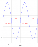
As might be expected, the error extracted increases dramatically, while the input to the complimentary buffer shows the great ''predistortion'' the correction loop has to generate to give a virtually distortionless output.
Note that if the output generates significant distortion, then sufficient headroom must be provided by the driver preceding the output stage to accommodate the potentially large ''predistorted'' waveform at its input.
Note that if the output generates significant distortion, then sufficient headroom must be provided by the driver preceding the output stage to accommodate the potentially large ''predistorted'' waveform at its input.
Attachments
Andy_c wrote:
When I do this simulation with the Cordell model, nulled, the unity gain f is 750kHz with 1 deg of margin. Pretty unstable - no wonder an output L is mandatory. To resolve this the outter loop phase margin needs to be widened by at least 45 deg.
Possible...but tricky.
The outter loop gain of the EC will reveal the cause of the peaking. Would you measure the outter loop gain with the 2uF and tell me the unity-gain f and the phase margin?Yes, with the stipulation that I'm referring to the innermost loop of the error correction circuit. The trick seems to be to avoid peaking in the frequency response of the output stage. This seems to be more difficult as more output devices are parelleled. The peaking in output stage magnitude response seems to cause an increase in the inner loop gain of the error correction
When I do this simulation with the Cordell model, nulled, the unity gain f is 750kHz with 1 deg of margin. Pretty unstable - no wonder an output L is mandatory. To resolve this the outter loop phase margin needs to be widened by at least 45 deg.
Possible...but tricky.
- Home
- Amplifiers
- Solid State
- Bob Cordell Interview: Error Correction