Re: The bam challenge
Brian,
Which is the point of this personal crusade commited to erase the concept or error correction from the face of the Earth?
Haven't we been clear enough to express any form of feedback based topology cannot possibly cancel error without violating causality?
Haven't we been equally patient and persistent remarking error correction is a strategy, and is implemented in a different circuit realization?
Haven't we recognized both error correction - in the real world - and global negative feedback - in the real world - converge to equal transfer expressions?
Does it harm to be open-minded and in looking at a problem gather a different insight and spawn novel results? Recall Bob said in an earlier post had he suspected in advance error correction an negative feedback were so closely related, he should not have persued developement of his amplifier, depriving the art of a fine accomplishment.
Sincerely, I should realy want to understand the reasons that drive you to this fundamentalist stance.
Rodolfo
traderbam said:
This is the hypothesis that MUST BE TRUE if the belief that "error correction" cancels output error and is not just NFB in disguise is true.
I challenge ANYONE here to find me ANY linear function L that meets this claim for ANY non-linear function N.
Brian
Hint: you are wasting your time trying. 😉
Brian,
Which is the point of this personal crusade commited to erase the concept or error correction from the face of the Earth?
Haven't we been clear enough to express any form of feedback based topology cannot possibly cancel error without violating causality?
Haven't we been equally patient and persistent remarking error correction is a strategy, and is implemented in a different circuit realization?
Haven't we recognized both error correction - in the real world - and global negative feedback - in the real world - converge to equal transfer expressions?
Does it harm to be open-minded and in looking at a problem gather a different insight and spawn novel results? Recall Bob said in an earlier post had he suspected in advance error correction an negative feedback were so closely related, he should not have persued developement of his amplifier, depriving the art of a fine accomplishment.
Sincerely, I should realy want to understand the reasons that drive you to this fundamentalist stance.
Rodolfo
Re: Re: The bam challenge
http://www.diyaudio.com/forums/showthread.php?postid=1069128#post1069128
http://www.diyaudio.com/forums/showthread.php?postid=1067776#post1067776
ingrast said:
Haven't we been clear enough to express any form of feedback based topology cannot possibly cancel error without violating causality?
Rodolfo
http://www.diyaudio.com/forums/showthread.php?postid=1069128#post1069128
http://www.diyaudio.com/forums/showthread.php?postid=1067776#post1067776
Mikeks wrote:
This sounds erroneous, but the language is ambiguous. Show me what you think the loop gain equations are in both cases and I'll check them (and please don't offer me a bunch of lazy links, ok?).With the usual single-ended NFB, loop-transmission does NOT increase with the quantity (''error'') we wish to eliminate, while with error-cancellation-by-NFB, loop transmission is directly proportional to extracted error.
Interesting reaction, Rodolfo. 😀
Not sure what you are talking about.
I made an argument against the notion that Hawksford EC is somehow to do with "cancelation" rather than feedback.
So?
Not sure what you are talking about.
I made an argument against the notion that Hawksford EC is somehow to do with "cancelation" rather than feedback.
So?
traderbam said:.....
I made an argument against the notion that Hawksford EC is somehow to do with "cancelation" rather than feedback.
.....
Brian, you know as well as I there is not in the real world anything like cancellation in a strict sense. I will not make you the offense of delving into this fact in greater detail.
Yet we routinely use the term "cancellation" in everyday work as a handy tag for a given design strategy. We talk long distance with help of echo chancellers, or cancel poles in circuit synthesis to achieve desired results.
Error correction equally models a topology where an error can effectively be cancelled given an idealized model. This is in constrast with negative feedback where not even in an idealized model the error can be nulled.
I fail to see alternative forms of putting this in a more persuasive form, and what begun in mild amusement is approaching exasperation, and really want to get over this for good. Apologies if I sound harsh, there are no personal implications either, and I consider you above all a proficient person worth my esteem.
Rodolfo
traderbam said:Bob wrote:
Is it the nulling "miracle" that is the sticking point to accepting the equivalence to NFB?
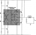
This is simple to explain. You already know that fig 4 below is Hawksford (only feedback correction: b=0).
The gain G = Vo/Vin = N/(1 - a + N)
The sensitivity of this to N, dG/dN = (1 - a)/(1 - a + Na)^2
The sensitivity to N, ie: the sensitivity of gain to error in N, is minimized when a = 1 and is increased when a > 1 or a < 1. The sign of the sensitivity changes through the null point.
When a = 1 the theoretical loop gain is infinite. It won't be in practice, as Rodolfo has shown, because the PFB contains at least one pole. At the null setting the total distortion will not be zero in a real circuit.
Hi Brian,
Looks good to me. Most, if not all, of you guys are right within your own paradigm. I agree that the block diagram equivalences you have shown are a correct and legitimate way to look at the EC, but they are also not the only way to look at it, and they may obscure some realities of implementation detail that are important in the real world. The Devil is in the details. If you tried to implement your block diagram in a conventional and straightforward way, with a huge piece of gain approaching infinity, in most cases I don't think it would work as well as the Hawksford actual architecture. This is not to say that anyone is wrong, or that one way of looking at it is better than another. Each view brings different, and equally valuable insights.
Peace,
Bob
traderbam said:Show me what you think the loop gain equations are.....
Have you checked....?

Hi Bob.
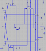
What do you think of Hawksford's alternative to defining the error amplifier's collector loads below?
I am presently mulling over how Yokoyama could be similarly implemented.
I suspect, for a start, that a complimentary pair of emitter-coupled stages (as error extractors) may be necessary.
What do you think of Hawksford's alternative to defining the error amplifier's collector loads below?
I am presently mulling over how Yokoyama could be similarly implemented.
I suspect, for a start, that a complimentary pair of emitter-coupled stages (as error extractors) may be necessary.
Attachments
Re: The nulling feature explained, part 2
Hi Brian,
I thought all the values you needed were in the MOSFET amplifier paper on my web site. I think only the transistor types are lacking. Is that what you needed?
Bob
traderbam said:Your simulation results make sense to me, Tom.
Have you got those component values handy, Bob?
Hi Brian,
I thought all the values you needed were in the MOSFET amplifier paper on my web site. I think only the transistor types are lacking. Is that what you needed?
Bob
ingrast said:
...Error correction equally models a topology where an error can effectively be cancelled given an idealized model. This is in constrast with negative feedback where not even in an idealized model the error can be nulled...
Rodolfo
The exasperation exits on both sides, I can’t see why such reasonable, capable people can’t recognize such a simple erroneous pattern of thought when repeatedly pointed out to them.
The linear model of the Hawksford/Cordell error correction mechanism we are discussing is equivalent to a 2 degree of freedom linear feedback control system – look it up, understand the distinction between 1 degree of freedom “error feedback” and a 2 degree of freedom feedback systems.
Then a simple linear algebra/block diagram/signal flow graph manipulation result is that the linear model of any implementation of a 2 degree of freedom linear control system can be transformed to any other, including the Hawksford/Cordell block diagram.
The recognition of the equivalence lets us confidently predict that the limitations and potentialities of all such 2 degree of freedom linear systems are identical and well treated by linear control theory.
One of those results of feedback control system theory is that we cannot perfectly correct the errors of an uncertain plant/or injected disturbances without the equivalent of infinite gain.
When you say that errors can be exactly cancelled in an ”idealized” model you have simply overdone the “idealization” by implicitly incorporating infinite gain.
This is why there is so much heat from this side of the argument when you say “error correction” is something “fundamentally different”, yes different from 1 degree of freedom “error feedback” no not different, new or even distinguishable from 2 degree of freedom linear control systems
Re: Hi Bob.
Continuing from here.
Something roughly like this:
mikeks said:What do you think of Hawksford's alternative to defining the error amplifier's collector loads below?
I am presently mulling over how Yokoyama could be similarly implemented.
I suspect, for a start, that a complimentary pair of emitter-coupled stages (as error extractors) may be necessary.
Continuing from here.
Something roughly like this:
Attachments
traderbam said:Does the output stage overshoot at all on its own into 2uF?
Okay I just looked at this. If you do a sim of the square wave response of Bob's output stage, you'll see that with an 8 Ohm load, there is some overshoot. This appears to be caused by its transfer function having a zero on the negative real axis, like a slightly overcompensated scope probe. A low-pass filter at the input takes care of this.
When I do a sim of my circuit with a 2 uF load, this overshoot also appears and is cured the same way, with an input LPF. With the LPF, its square wave response into a 2 uF load looks like a single-pole circuit - no overshoot, no ringing. The highest LPF -3 dB freq that fixes the overshoot is 660 kHz. When put into a real-world amplifier, it would seem to be a non-issue, since the bandwidth of the amp should be limited either by caps in the feedback loop, an input LPF or both.
This overshoot is also present in my design with an 8 Ohm load. I suspect it's a side-effect of the error correction.
"Peace" 🙂 good idea.
Bob wrote:
Bob wrote:
Thanks for the thumbs up. I agree completely that the focus should be on the implemenation detail.Looks good to me. Most, if not all, of you guys are right within your own paradigm. I agree that the block diagram equivalences you have shown are a correct and legitimate way to look at the EC, but they are also not the only way to look at it, and they may obscure some realities of implementation detail that are important in the real world. The Devil is in the details.
The crux of the mattter for me is whether a PFB gain block works better in practice than a conventional gain block. At the moment, I think not for a number of reasons which I shall attempt to explain.If you tried to implement your block diagram......I don't think it would work as well as the Hawksford actual architecture.
Bob wrote:
Yes, that would be useful. I want to try to mimmick your results as closely as possible. By the way, which of the resistors did yout tune if any? I notice in your paper that you suggest a resistor in the PFB loop, between the junction of the 330 ohm resistors and the 27 ohm resistors. I'd like to make the LF loop gain comparable...I realise this may be tricky unless you've measured it in the specific circuit you built. Based on your THD improvement measurement I'd guess the loop gain of the EC was about 30dB at 20kHz.I thought all the values you needed were in the MOSFET amplifier paper on my web site. I think only the transistor types are lacking. Is that what you needed?
jcx wrote:

My insistance is because I believe the misconception can actually lead to narrow thinking...specifically, the failure to see a simpler topology that will lead to a simpler implementation.
The recognition of the equivalence lets us confidently predict that the limitations and potentialities of all such 2 degree of freedom linear systems are identical and well treated by linear control theory.
One of those results of feedback control system theory is that we cannot perfectly correct the errors of an uncertain plant/or injected disturbances without the equivalent of infinite gain.
When you say that errors can be exactly cancelled in an ”idealized” model you have simply overdone the “idealization” by implicitly incorporating infinite gain.
My insistance is because I believe the misconception can actually lead to narrow thinking...specifically, the failure to see a simpler topology that will lead to a simpler implementation.
Attached is an article on the Quad 405 amplifier, a commercial error cancelling amplifier. Can this be modelled simply as a feedback amplifier
http://quad405.com/currentdumping.pdf
Stuart
http://quad405.com/currentdumping.pdf
Stuart
Mike, do me a favour and post the two digrams and the two loop gain equations. I can't deal with all these links, etc.Have you checked....?
This is the problem: you blithely persist in flagrant error for hundreds of posts merely because you cannot be bothered to read posts other than your own!
http://www.diyaudio.com/forums/showthread.php?postid=1069151#post1069151
http://www.diyaudio.com/forums/showthread.php?postid=1069151#post1069151
- Home
- Amplifiers
- Solid State
- Bob Cordell Interview: Error Correction