mikeks said:I suppose you're right.
What bugs me is the Lipshitz/Vanderkooy assertion in that paper that no true cancellation can occur with this arangement unless you have infinite loop gain.
I just cannot see it, and it is constantly gnawing away at moi.
PPMFJI. I've been watching it happen on my simulator screen, most of the afternoon, in a new amp's simulation: With relatively low feedback gain, the cancellation will be imperfect. The more gain there is in the feedback loop, the closer to perfect the cancellation gets. BUT, _that_ means that the feedback loop then gets a smaller and smaller error signal. And, also, the cancellation effect increases more slowly than the feedback loop's gain. As the error gets vanishingly small, a real system has already run out of feedback gain, and an ideal system's feedback gain goes to infinity.
- Tom Gootee
mikeks said:
Michael, in your equation, looking at the original (fig 1) diagram one can see the cancellation condition is K2.K3=1, this is crucial for error correction to be such, any other choice is not error correction and cannot be considered and compared as such.
Substituting, the result not unexpectedly is G = K3, and the contribution of K1 disappears.
In my case, the cancellation condition 1/S-B=0, exactly the same, the result not unexpectedly is G =A', the contribution of A disappears.
In neither case the positive feedback is obvious algebraically, because de double loop topology conceals it, better said, cancels the inherent pole at DC.
Rodolfo
Rodolfo
Then your system was unbalanced, in all probability, for at balance the following obtain:
http://www.diyaudio.com/forums/showthread.php?postid=1067428#post1067428
http://www.diyaudio.com/forums/showthread.php?postid=1067431#post1067431
http://www.diyaudio.com/forums/showthread.php?postid=1067428#post1067428
http://www.diyaudio.com/forums/showthread.php?postid=1066204#post1066204
http://www.diyaudio.com/forums/showthread.php?postid=1067428#post1067428
http://www.diyaudio.com/forums/showthread.php?postid=1067431#post1067431
http://www.diyaudio.com/forums/showthread.php?postid=1067428#post1067428
http://www.diyaudio.com/forums/showthread.php?postid=1066204#post1066204
Hi Rodolfo,
Compare terms here:
http://www.diyaudio.com/forums/attachment.php?s=&postid=1066961&stamp=1164669314
and here:
http://www.diyaudio.com/forums/attachment.php?s=&postid=1066204&stamp=1164563348
and see what you come up with (at balance) in respect of closed-loop gain and loop-gain.
From this equation, it seems the condition for positive feedback is |K+error|<1.
Can you conceive of a situation where this might occur?
Bob Cordell said:
..... It gnaws away at me, too. I would think it will tend to gnaw away at anyone who has twiddled that pot. Go figure.
I was never totally happy with the way they put things in that paper, but I guess I just learned to live with it. .....
Bob
This thread has taken now an interesting turn again.
My view at least, and of course can be falsified if wrong, goes along this way.
Given a physical system with inherent transfer error, there is absolutely no way to correct it only by taking action "after the fact".
The rationale is, once an infinitesimal deviation occurs, there is no way for a feedback / feedforward mechanism to erase it as if it had never happened in the first place. This should be a time paradox, but this is precisely what complete correction means in the first place. Second best is to reduce it to vanishingly small levels, accepting never to erase it completely.
I also mentioned feedforward for, despite it has been said for example in the Liptshitz Vanderkooy paper, it must be accepted the error is computed a some instant in time, but cannot be added with zero delay (it must be amplified to be injected). This may have no practical consequences, for this delay can be made as small a technology allows without compromising stability. But cannot accomplish complete correction in a strict sense.
Turning back to feedback, in the form of error correction and following the previous line of thought, it is apparent one wants to apply the correction as soon as possible, that is, to have the highest practical processing bandwidth. This is precisely what error correction implies.
For negative feedback, the asymptotic requirement is infinite gain. This can be seen also as a zero delay equivalent, for it means an infinitesimally small departure instantaneously elicits an infinitely large corrective action.
Both approaches have been shown to be dual faces sharing a common mathematical description. This is what I hinted in a previous post as a joke Nature is playing, showing the way for a deeper reality. In fact I have been toying with the idea of proving negative feedback and error correction belong to an equivalence class where a functional transform turns one into the other. This is well above my par in math, so I was thinking to contact people form the Mathematics Institute at the Faculty. A good hint in this direction is both lead to the same description of a circuit, but this is not what I am seeking as a result.
Anyway, it does not harm to poke around this garden.
Rodolfo
abc11 said:Hi mikeks
can you please tell me whats error correction in summary
i dont understand it unless someone tells me what itis
please help
kind regards
Alfred
http://www.diyaudio.com/forums/showthread.php?postid=1059967#post1059967
The nulling feature explained, part 2
Your simulation results make sense to me, Tom.
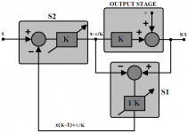
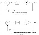
Let's look again at Hawksford. What the fig 4 system actually gives you is the ability to adjust the loop gain of the system by means of "a". When a = 1 the loop gain is maximized. In a real circuit there will be at least one pole in the loop and the unity gain bandwidth will not be infinite. As you change "a" you both change the low frequency loop gain and move the pole frequency.
This is very much like the behaviour of an op-amp integrator where the -'ve input is fed by a current signal and the output is connected to the -'ve input with a capacitor. If a variable resistor is placed in parallel with the capacitor the integrator response gains a pole whose frequency can be varied. The null condition, when a=1, is equivalent to the resistor having infinite value.
The loop gain of Bob's output stage exhibits this behaviour in simulation too.
My proposition is that this ability to adjust the positive feedback and minimize the pole frequency is very useful, but not as useful as using a fixed integrator (always at perfect null) and varying the gain bandwidth product of the loop. For it is the GBP of the loop (with adequate phase margin) that utlimately drives how powerful the distortion reduction can be.
In fig 5, this means the forward gain function, G, would be a pure integrator with a GBP adjustment. More on this after Bob's output stage has been analyzed in full.
Have you got those component values handy, Bob?
Your simulation results make sense to me, Tom.
Let's look again at Hawksford. What the fig 4 system actually gives you is the ability to adjust the loop gain of the system by means of "a". When a = 1 the loop gain is maximized. In a real circuit there will be at least one pole in the loop and the unity gain bandwidth will not be infinite. As you change "a" you both change the low frequency loop gain and move the pole frequency.
This is very much like the behaviour of an op-amp integrator where the -'ve input is fed by a current signal and the output is connected to the -'ve input with a capacitor. If a variable resistor is placed in parallel with the capacitor the integrator response gains a pole whose frequency can be varied. The null condition, when a=1, is equivalent to the resistor having infinite value.
The loop gain of Bob's output stage exhibits this behaviour in simulation too.
My proposition is that this ability to adjust the positive feedback and minimize the pole frequency is very useful, but not as useful as using a fixed integrator (always at perfect null) and varying the gain bandwidth product of the loop. For it is the GBP of the loop (with adequate phase margin) that utlimately drives how powerful the distortion reduction can be.
In fig 5, this means the forward gain function, G, would be a pure integrator with a GBP adjustment. More on this after Bob's output stage has been analyzed in full.
Have you got those component values handy, Bob?
Attachments
ingrast said:The rationale is, once an infinitesimal deviation occurs, there is no way for a feedback / feedforward mechanism to erase it as if it had never happened in the first place. This should be a time paradox, but this is precisely what complete correction means in the first place. Second best is to reduce it to vanishingly small levels, accepting never to erase it completely.
Rodolfo
Hawksford appears to disagree:
http://www.essex.ac.uk/ESE/research...alization of error correctiona amplifiers.pdf
This Error-Cancellation method is quite interesting. I haven't had time to read the papers or re-derive it in mathematical form. No need. But I happened to be working with a new amplifier's simulation, when I read one of the messages about error cancellation. So I decided to just try it, in LT-Spice.
Interestingly, the "input + correction" signal that gets applied to the chipamp's input (i.e. just after the summing junction) looks almost EXACTLY the same as it does in the classical-feedback version that I already had finished.
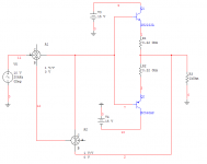
(I'm sorry if mentioning chipamps is heretical, in this group, but,) I was designing a control system to wrap around a single-IC power amp (e.g. LM3886 et al, except the only Spice model I could find that was at-all similar was for the OPA541(E)). In addition to the standard out-to-neg inner feedback loop around the power amp, I have an outer loop, with an opamp ahead of the power amp, so the power amp is inside the opamp's FB loop, in the forward path, with the chipamp's output (eventually) connected to the opamp's neg input, and the input signal connected to the opamp's pos input. The chipamp/inner loop is set for a gain of 20.
The error-cancellation loop was very easy to slap together, with a couple of dual opamps.
Having not read the papers about it, my system might be simplistic: To get the error signal, I merely scale the output by the inverse of the forward gain, using a resistive divider (with buffers before and after the divider), and then subtract the input from it, by using an opamp as a differential amplifier. The error signal is then amplified and subtracted from the input signal (using the opamp that feeds the chipamp's pos input).
It works. But, to get it to give THD that's as low as my classical version's, I'd probably need to tweak or servo the output offset voltages of all of the opamps in the feedback loop, to make the error signal more accurate.
I also created a "Classical/EC Hybrid" version of the same amplifier circuit, by simply adding the error cancellation loop to the completed design that already had the classical-approach outer feedback loop, subtracting both of the feedback signals at the same point.
I must say that adding the still-imperfect EC loop to the classical system made a major improvement! I thought that I had wrung almost every last bit of performance out of that system, already, and had THD figures of 0.001926% @ 20 kHz and 0.000330% @ 1 kHz. BUT, after adding the EC loop (but not fixing any of the offset voltages in it), the THDs went to 0.001166% @ 20 kHz and 0.000048% at 1 kHz! And everything else still looks good, too.
I think I'll keep it.
- Tom Gootee
Interestingly, the "input + correction" signal that gets applied to the chipamp's input (i.e. just after the summing junction) looks almost EXACTLY the same as it does in the classical-feedback version that I already had finished.
(I'm sorry if mentioning chipamps is heretical, in this group, but,) I was designing a control system to wrap around a single-IC power amp (e.g. LM3886 et al, except the only Spice model I could find that was at-all similar was for the OPA541(E)). In addition to the standard out-to-neg inner feedback loop around the power amp, I have an outer loop, with an opamp ahead of the power amp, so the power amp is inside the opamp's FB loop, in the forward path, with the chipamp's output (eventually) connected to the opamp's neg input, and the input signal connected to the opamp's pos input. The chipamp/inner loop is set for a gain of 20.
The error-cancellation loop was very easy to slap together, with a couple of dual opamps.
Having not read the papers about it, my system might be simplistic: To get the error signal, I merely scale the output by the inverse of the forward gain, using a resistive divider (with buffers before and after the divider), and then subtract the input from it, by using an opamp as a differential amplifier. The error signal is then amplified and subtracted from the input signal (using the opamp that feeds the chipamp's pos input).
It works. But, to get it to give THD that's as low as my classical version's, I'd probably need to tweak or servo the output offset voltages of all of the opamps in the feedback loop, to make the error signal more accurate.
I also created a "Classical/EC Hybrid" version of the same amplifier circuit, by simply adding the error cancellation loop to the completed design that already had the classical-approach outer feedback loop, subtracting both of the feedback signals at the same point.
I must say that adding the still-imperfect EC loop to the classical system made a major improvement! I thought that I had wrung almost every last bit of performance out of that system, already, and had THD figures of 0.001926% @ 20 kHz and 0.000330% @ 1 kHz. BUT, after adding the EC loop (but not fixing any of the offset voltages in it), the THDs went to 0.001166% @ 20 kHz and 0.000048% at 1 kHz! And everything else still looks good, too.
I think I'll keep it.
- Tom Gootee
Tom wrote:
If you measure the total feedback factor with and without the "EC" you should expect its ratio to be similar to the THD ratio.
Brian
The joys of nested feedback.I think I'll keep it.
If you measure the total feedback factor with and without the "EC" you should expect its ratio to be similar to the THD ratio.
Brian
ingrast said:
Michael, in your equation, looking at the original (fig 1) diagram one can see the cancellation condition is K2.K3=1, this is crucial for error correction to be such, any other choice is not error correction and cannot be considered and compared as such.
Rodolfo
True.
Note that although the product of the gains across the summers has to be unity for balance (error cancellation), this does not apply to the system's loop-gain.
Break away group?
I think this thread has become a three-ring circus.
My particular interest is in analyzing Bob Cordell's output stage at an engineering level and then exploring whether it can, 22 years on, be improved. Bob Cordell, Andy_c and Anatech have signalled some interest too.
Do you guys or anyone else want to have a focussed discussion? Should I start a fresh thread? Otherwise I'll drop it or just correspond by email.
mikeks said:
Hawksford appears to disagree:
http://www.essex.ac.uk/ESE/research...alization of error correctiona amplifiers.pdf
There is a way, but I doubt it fails to be a mere curiosity.
If you compute the error, and feed forward *after* a delay exactly matching the error extraction circutiry so as to align in the same time frame, it works.
A possible particular implementation as shown by Hawksford uses an inductor and matching, but I doubt it resists loading with the usual speaker.
Rodolfo
I have this inside my hard disk, don't know where its from
"I'm looking to have an amp that requires no output inductor and am trying to design it
so it will produce a full power square wave at 20 kHz with no ringing or overshoot into
a 2 uF capacitive load, yet still have low sine wave distortion. The square wave requirement
into a reactive load has meant having a low unity loop gain frequency, only a little over
100 kHz, so the feedback at 20 kHz is quite low. This is why I was interested in
the error correction technique. I have an LTSpice simulation of the Cordell circuit,
and am now playing with a simulation of an error-corrected version of an output stage
that looks like a mixture of the Cordell circuit and the Holton AV800 (14 output FETs total).
I'm having a tough time with it. If I compensate the error correction loop so it
works well with an 8 Ohm load on the output stage, it oscillates with 2 uF.
If I compensate the loop so it works well with 2 uF, it oscillates with 8 Ohms.
If I overcompensate it so it's stable with both, I get no improvement in 20 kHz harmonic
distortion over the uncompensated design - yet there are still odd frequency response
quirks introduced.
It appears at first glance that the stabilization of the error correction feedback loop
should be easy, since the loop gain is low. But one problem is that the loop in its
idealized form tries to force the output to equal the input independent of frequency.
So at high frequencies, large error correction voltages will appear that are compensating
for frequency response effects. In the ideal case, you'd want to low-pass filter
the picked-off input of the output stage with a filter that very closely matches
the frequency response of the output stage, prior to subtracting it from the picked-off
output to get the error voltage. If the frequency responses matched perfectly,
you'd have an error correction voltage that only compensated for distortion
and not frequency response effects. But the Cordell/Hawksford circuit cross-couples
the picked-off input to both sides of the difference circuit, making this impractical.
However, if you look at the schematic in the Halcro patent, you'll see he modifies it
so that a level-shifted version of the output is only connected to the base of the
error-correction transistor, and the level-shifted input is only connected to the emitter.
This allows separate filtering of the picked-off input to match the output stage
frequency response. This works great with an 8 Ohm load. But when 2 uF is put in
parallel with the 8 Ohms, the bandwidth of the output stage drops dramatically.
Now there's a big frequency response mismatch. When this happens,
the loop gain of the error correction loop (as simulated using the Middlebrook technique),
though it is only about -40 to -50 dB at low frequencies, jumps to about +15 dB in the
low MHz range, with unpredictable, uncontrollable phase.
This is what causes the instability I'm fighting.
Actually, I'm about ready to give up on it. Even when the compensation works well,
it seems to introduce complex poles into the frequency response of the output stage,
making the phase drop off more rapidly than one might guess by looking at the magnitude plots.
Also, the reduction of distortion with the 7 p-channel, 7 n-channel output stage is not
as dramatic as with a single device. This is due to the distortion being fairly low to
begin with, due to the higher effective gm from having so many devices in parallel.
Also, upping the bias current to 150 mA per device keeps the distortion in check.
I can get good transient response without the error-correction stuff, even with a 2 uF load.
If you want to get rid of the servo, I would also suggest getting rid of the error correction.
In my experience you are better off just adding another pair (or two or three) of output devices.
This is particularly true for this design as the triple emitter-follower output stage
will be able to drive low impedance loads quite well.
lumanauw said:I have this inside my hard disk, don't know where its from
That was from me. I was trying to do all this stuff without an output inductor. Adding the output inductor and its resistor, etc fixes all the problems I mentioned. Of course I was no longer able to achieve the goal of no ringing with square waves into a 2uF load. I've reached the conclusion that such a goal is a "fool's errand". Chalk that one up to inexperience.
- Home
- Amplifiers
- Solid State
- Bob Cordell Interview: Error Correction