It’s fan operated so once temperature reaches 75 degrees it switches on. But it sucks the air out as opposed to blowing in so keeps better ambient temperature. Rather than just blasting cold air into the unit.
I'm going to disagree with you there looking at your enclosure setup with the Mosfet on a flat surface...
It probably will never get to the temp to activate the fan.
It's your build and I only giving my 1p to it.
It probably will never get to the temp to activate the fan.
It's your build and I only giving my 1p to it.
Not sure what you mean. Flat surface?
You have an aluminium base with the tranny on then the large heat sink and pcb which sits off that by 10mm and heat sink is bolted to the aluminium base plate which is then bolted to the chassis. So not lost there.
You have an aluminium base with the tranny on then the large heat sink and pcb which sits off that by 10mm and heat sink is bolted to the aluminium base plate which is then bolted to the chassis. So not lost there.

Let me try to explain like I would do to a 5 year old...
Mosfet are bolted to a flat bit of aluminium (Well "L" shaped) correct ?
So no fins or anything correct ?
They are mounted to the sides of the enclosure correct ?
Fan and "inlet" window are mounted in the centre of enclosure ( Front and Back) correct ?
So air flow takes the path of least resistance so it's going in and straight out in a straight "line" or do you expect it to go around corners ?
I know it will suck the hot air inside but efficiency is going to be in the toilet and if you read the instruction for those modules they say to attach heatsinks actually just looking at them anybody can see that.
Again is your build and your rules but what happened to common sense ?
Last edited:
Hot air rises cool air sinks then as the air becomes slightly warmer it rises. So you have ambient temperature throughout the cabinet.
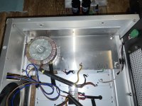
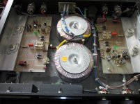
The cabinet is a military spec ex 300 watt AF amplifier and I think the fan design obviously worked powering 6 power mosfets on heatsinks untold can mosfets 12kg mains transformer 6kg output transformer 2 stepdown transformers and 4 6"x 2" capacitor along with point to point wiring etc etc in other words it got hot and that cooling system kept the whole unit cool. So really what your saying is air does not go round corners em think you need to think on that one. But you could just turn the heatsinks round straight down the middle and blow cold air all over them. Dropping temperature rapidly as opposed to gradually. Is that good for the mosfets freeze em then let them get hot again then freeze em. Personally thats gonna do more damage than good.
But if you now better then feel free to improve on a military spec design and I'll copy it. Be more than happy to.
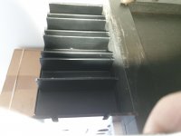
What I mean is that "L" profile is nowhere close to what you need in terms of cooling
For you to have and idea here is the BK MF450 module
PS: I do work with military stuff every single day (aircrafts, radars, missiles you name it )
For you to have and idea here is the BK MF450 module
PS: I do work with military stuff every single day (aircrafts, radars, missiles you name it )
Attachments
Last edited:
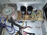
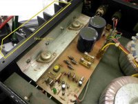
And no capacitors after the rectifiers
Like I mentioned before your build your rules...
There is nothing I can say for you to understand it.
I give up
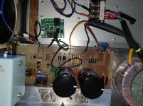
B. K Electronics Dmp Mxf-200 High Power Professional Mosfet Amplifier 100w Ch
Can you see the heatsinks ?
Like I mentioned before your build your rules...
There is nothing I can say for you to understand it.
I give up
B. K Electronics Dmp Mxf-200 High Power Professional Mosfet Amplifier 100w Ch
Can you see the heatsinks ?
Last edited:
So yes, turning the modules around and blowing the air across them will cool them far better than the way they are at the moment..But you could just turn the heatsinks round straight down the middle and blow cold air all over them. Is that good for the mosfets freeze em then let them get hot again then freeze em. Personally thats gonna do more damage than good.
What will do more damage is to have poor heatsinking and inadequate cooling which will cause your output devices to become too hot and subsequently fail.
This is exactly what RS232 was trying to tell you:-
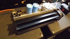
So you now have all the information you need to set the bias and check the offset voltage.Just don't forget to add a heatsink to the mounting brackets because they are not enough to remove the heat from the power mosfets.
PS: according to the App note your power supply is fine for those 2SJ50/2SK135 mosfets and 80 to 120mA bias
See pic. Look familiar?
Attachments
I may be wrong, but I think RS232's point is/was that there isn't enough heat sink area for the MOSFETs. Getting the BTUs out of the cabinet is an entirely separate issue -- one that is handled just great by the setup you have.
If you set the idle current to 100mA, the idle power dissipation is almost 12W (rounded); set it to 140mA and it's 16W. And that's just the beginning - no signal.
The 25 or 30 square inches of 1/4 or 5/16-thick aluminum just doesn't provide enough surface area to transfer the heat to the surrounding air. Just attach an standard extruded section, 2-inches deep or so vertical fins, maybe twice the height of the vertical section of the MOSFET mounting bracket, and maybe 1½ or 2 times deeper front-to-back (relative to the unit overall), one for each bracket.
The angle brackets are really intended to serve as mounting and thermal-transfer elements, not fully-satisfactory dissipating surfaces. Attaching it to another, thinner cross-section simply puts too much additional thermal resistance in between the hot TO-3s and the convecting surface.
Cheers
edit: Sorry. I'm too slow, sidsparks already made my points .. 😱
Last edited:
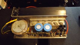
Forgot the thermistor will be sitting inbetween the mosfets on the heatsinkpp set at 75 degrees then the relay will turn the fan on.
So things on outside of unit thermistor inbetween the mosfets fan which i think is more than adequate to keep things at an ambient temperature. These as far as I know require heat to get the best out of then. Blowing very cold air straight over then its gonna reduce heat drastically so the poor mosfets are hot the suddenly cold. I'm sure if you continue to do that your gonna do damage. Bit like putting ice in sink then pouring ambient temperature over the ice what happens to the ice it melts. So as Rick said I'm sure that configuration is more than adequate to keep things warm not overheating.. plus it's only 100 watt not 450 watts. Think big difference in amount of heat generated.
So things on outside of unit thermistor inbetween the mosfets fan which i think is more than adequate to keep things at an ambient temperature. These as far as I know require heat to get the best out of then. Blowing very cold air straight over then its gonna reduce heat drastically so the poor mosfets are hot the suddenly cold. I'm sure if you continue to do that your gonna do damage. Bit like putting ice in sink then pouring ambient temperature over the ice what happens to the ice it melts. So as Rick said I'm sure that configuration is more than adequate to keep things warm not overheating.. plus it's only 100 watt not 450 watts. Think big difference in amount of heat generated.
A set of these will be on side of unit.
Your missing the point.
You don't need those heatsinks on the outside if your using a fan inside.
Also they won't work effectively due to the thermal resistance of the steel case.
That's beside the point anyway as you have already made the decision to go down the fan cooled route.
Sid.
Well that don't work. You cannot trim this unit with the maplin instructions at all. So your running from b+ to fuse well I've done that following the instructions well I've measured current on both +/- sides and both just sitting at 1.6mA The trimmer is not moving the current at all!!!!
Plus the left module 26v on output!!!!!!!!
Right module 0.8mV correct.
So not quite sure whats going on here. I've put the 500mA fuses in as per instructions as well. Neither of which have blown.
The left module tranny is pushing out a couple more volts higher than right tranny.
So L1 is 26v as expected L1 right module 0.8mV perfect.
So lost on that one.
LEDs nice and bright.
All I can think of is there's a connection loose somewhere or the trimmers both not working but doubt that. So there's obviously a different set up sequence. I did not try trimming on the output terminals. The left trimmer set around 640r right 550r. So in theory if I set the left to 550r then output should read 0.8mV?
So nothing is getting hot nothing has blown so could be meters but I've used the 4 I've got plus my valve meter and still getting the same readings.
What I don't understand is you have the +/- running through the fuses. So you install 500mV fuses to protect circuit but you can also adjust the bias via that method with the fuses insitu?
Yeah I know that Side thanks for that which was what I was trying to get across hence the pic I posted of the same modules has no fan it's using the heatsinks on outside of case. I think Rs322 was going on about the BF transistors and putting mini heatsinks on them. But all these MF100 modules do not have any on them at all. Then RS322 sent picture of MF450 modules assuming there 450 watts then yes I can see adding them to the BFs then. Lots of heat. Plus I was trying to explain how my system works the fan draws air in from front end via a filter and gradually pulls down the heat in the cabinet. It's also controlled via a thermosistor so again tried to explain that to no avail. The heatsink is more than adequate for the mosfets attached to it from wattage point of view. Plus if everything in there is gonna get that hot then there's a fault or is it called thermal runaway. Plus is it gonna be pushing 100 watts max in my house don't think so plus its not gonna get used as a PA for gigs parties etc so I can't actually see it getting up to 105 degrees and above. So it seemed kinda pointless really.
- Home
- Amplifiers
- Solid State
- BK Electronics mosFET 100 watt modules