You haven't considered the differences between the Maplin and the BK units in regard to the setup procedure.
The BK units have the power supply components on board ie fuses, rectifiers and smoothing caps.
The Maplin unit power supply components are completely separate to the main board.
This can be seen in the info that RS232 posted (#103)
Here's my suggestion:-
For each module one at a time
1. Remove the fuses.
2. Put 100r resistors across the fuse clips. (just wrap the wire ends around the clips)
3. Apply power
4. Measure the DC voltage at the output with respect to 0V. Make a note of it. Anything more than about 20-30mV and you have a fault.
5. If output voltage is ok then measure the AC voltage across one of the 100r resistors.
Note: This will not give an accurate current reading but it will tell you whether you're in the right ball park or if there is a fault. Make a note of this AC voltage reading
6. Report back here with the results.
What sort of meter are you using?
As you have already indicated that one module has 26V on it's output there is clearly a fault with it.
Sid
Cheers Sid yeah did throw me a bit. Knew it was different.
Anyhow I’ll do that tomorrow now had enough for today.
Cheers Chris
Anyhow I’ll do that tomorrow now had enough for today.
Cheers Chris

I thinks everybody made this mistake but this time my brain completely **** itself...
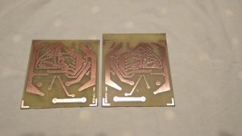
Printed the wrong way around (mirror image)
Transfer and developed it without spotting.
Drilled it and did I noticed ? Nop
Hell I even put the silkscreen on the other side wrong (again mirror image)
I suppose it's what happens when people get over the big 5 0
Printed the wrong way around (mirror image)
Transfer and developed it without spotting.
Drilled it and did I noticed ? Nop
Hell I even put the silkscreen on the other side wrong (again mirror image)
I suppose it's what happens when people get over the big 5 0
Right Sid just back from emergency vets errrrr never ending. Right I'll take these readings I'll just set it up. Problem only got 2 watt 100r so I'll run it through variac at 100vdc should be enough to light this up. Can't see it needing full 245vdc I get here or 250 in some cases as just 10m from sub station. So don't wanna overheat em.
So I can get mA reading on outputs? Negative obviously is on the 0v line on output. Or did you mean mV? Just don't want great big spark and buggar up one of me meters.
So I can get mA reading on outputs? Negative obviously is on the 0v line on output. Or did you mean mV? Just don't want great big spark and buggar up one of me meters.
Well that’s done. I think current way too high on left module and possible short somewhere.
All readings taken at 240vdc input.
Left module
Output 250mA slight spark on touching +ve and LED dims obviously pulling current as I’m taking reading.
Fuse 1 100r across resistor 3.9vac
Fuse 2 100r across resistor 3.9vac
Right module no spark or dimming of LED
Output 10mV
Fuse 1 7.3 vac
Fuse 2 7.3 vac
So could be a short, the tranny or earthing problem or trimmer set to low on left module. Pure speculation on my part.
Yes 0v -ve lead +ve lead to +ve on output as asked to do. Strange LED it just drained it. Other module fine as you can see. Only 10mA
Please don't tell us that you measured CURRENT on the speaker output ?
I know the J50/K135 is a very robust Mosfet pair but putting a shunt in the output is asking for trouble
I know the J50/K135 is a very robust Mosfet pair but putting a shunt in the output is asking for trouble
Yeah could have swarm it said measure mA on output only brief. That’s what happens when you have a stressful day and read mA as opposed to mV. Such is life.
Previous post no replyRight Sid just back from emergency vets errrrr never ending. Right I'll take these readings I'll just set it up. Problem only got 2 watt 100r so I'll run it through variac at 100vdc should be enough to light this up. Can't see it needing full 245vdc I get here or 250 in some cases as just 10m from sub station. So don't wanna overheat em.
So I can get mA reading on outputs? Negative obviously is on the 0v line on output. Or did you mean mV? Just don't want great big spark and buggar up one of me meters.
I thought the instructions I gave were clear and precise.
I asked you to measure DC Volts and AC volts only nothing else.
You didn't reply to the question "what sort of meter are you using"
Sid
I asked you to measure DC Volts and AC volts only nothing else.
You didn't reply to the question "what sort of meter are you using"
Sid
Not a problem doubt I’m the first and definitely will not be the last.
Use analogue digital and valve meters got around 6 in all.
Use analogue digital and valve meters got around 6 in all.
There where no big sparks or smoke etc so I very much doubt there's any damage done. If it had smoked or large spark or it just died then damage done. Most of these components seem pretty robust having done a fair bit of reading. Anyhow clear head today so I'll do it the proper way ha ha. I should and known better anyhow knew it was wrong. All meters are good quality not 12.99 from China jobbies and pretty darn accurate. I have blown one transistor before touching a leg slipping and hitting earth and spark well must of been 6" plus. Fuses went and it died. Replaced all worked fine again. I don't understand it really as quite a few of my valve amps tunners etc have bias test point's built in just makes life so much easier. All about cost cutting. Like expensive bit of kit with non sealed carbon track trimmers 20p each whacked in all for sake of saving few quid on production costs. Ridiculous.
Not happy with the 100r 2 watt resistor but gonna have to do got plenty of 180r plus. Or 0.1r.
Other meters high amp up to 50amps other goes down to micro amps resistor tester goes from 0.1 to 0.0001r scope two one valve from WW2 battle ship marconi TF801A sig gen veneer oscillator plus couple of superhets which can also use for testing purposes valve tester etc etc so got plenty of good test equipment shallcross which really good for testing condition of wiring very handy. Plus other gear dotted about.
No matter what type, how good or how expensive the meter is the problem is that by measuring ma/Amps you are applying a short to the output mosfets.
Yeah will see in a bit aye. Worst case senario just buy new pair. Like say not the first and won’t be the last we all get it wrong at times for sure.
As expected def fault left module
Input 245vdc
Left module
Ouput 38vdc
4.4vac fuse
Right module perfecto
16.6mV
4.1vac fuse
Input 245vdc
Left module
Ouput 38vdc
4.4vac fuse
Right module perfecto
16.6mV
4.1vac fuse
Okay so that's blow the speakers up jobby.
So trouble shooting open to possible reasons.
So we have the inductor certainly can't be that.
Then we have the source of mosfets.
Then onto the 2sa 872s.
I think I've got that right!
So can we rule out drain and gate circuit and move along circuit mentioned above?
TR4 5 6 & 7 ALL brand new. New 6.8k resistor and the 100r ones 2 watt but I've put 3 watt in. New trimmers 1k. Gate resistors changed to 270r as opposed to the 220r installed. That's it.
So no modifications. Now only thing I did do which Ivwish I had not was removing inductor and putting in new 100r as it was a pain to do and unnecessary. But can't see that causing a whopping voltage on the output.
Anyhow just my assumptions.
- Home
- Amplifiers
- Solid State
- BK Electronics mosFET 100 watt modules