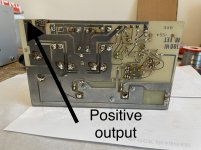
Work your way back from the output (forget inductor and associated components) look at the main (?) culprits like power mosfets and drivers removed them from circuit to test (can be done with them on the board).
Post picture of faulty module
Post picture of faulty module
Last edited:
Thanks I’ll do that the trs I tested out of circuit all okay. But as you say I’ll test in circuit see what I get in relation to the actual spec sheets for them. The left module was iffy to begin with so was not surprised but thought changing out the TRs would rectify the problem. But I expect it’s also thrown the bias out. But when 38v on output me jaw did drop down to floor and back up. Right I’ll get on with that. Super dooper keep me head nice and clear something to focus on.
Well found the culprits did think it was them anyway since taking mA readings ooooooopppppsssss the LED dimmed not so on other side. So it’s on right part of circuit. Everything else is after trimming pot to same resistance as the other bang on all over the circuit except 2 of the 2SA 872s. So fingers crossed that’s problem solved.
Take 5 then hook up and see if output has dropped. If does not then I’ll be lost.
Take 5 then hook up and see if output has dropped. If does not then I’ll be lost.
Well that did not work bum bum. But noticed when I pushed the k135 down hard it dropped straight to 1.5mV. So does that mean it just needs tighten up or it’s knackered?
Cheers Chris
Cheers Chris
Em give up something wrong tap the outputs move psu caps etc drops down to 1.5mV!
Did notice k135 one side is lifted not sure how that’s happened so it’s not sitting on mica or pressed against heat sink. Like say when tapped tends to drop right down otherwise it’s sitting at 38v now and 6.8k resistor got 50v on one side. Obviously drops as output drops.
So maybe new j50 k135 by loooks of it. Everything else is bang on with other module.
Do you mean the output voltage drops from 38Vdc to 1.5mV when you apply pressure?
If one side is lifted you may well have a connection problem.
Tighten the mounting screws, resolder the pins then check that the transistor case is isolated from the heatsink.
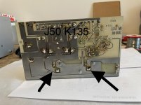
Take a picture of the solder side of the board.
Once you've done that check the output voltage again.
Sid
If one side is lifted you may well have a connection problem.
Tighten the mounting screws, resolder the pins then check that the transistor case is isolated from the heatsink.
Take a picture of the solder side of the board.
Once you've done that check the output voltage again.
Sid
Already did all that. No difference. I'll take picture of board underneath later. Bit fed up with it don't make any sense.
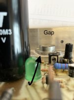
Yes if you tap j50 or k135 or move the +,ve pin around it all drops to 1.6mV which is more or less perfect 0mV. But the k135 is isolated from the heatsink via mica washers and compound but one side has a good 1mm gap from bottom of case to the mics washer. If that s gonna make any difference not sure but then it does not explain why itssame for J50 which is flat against heatsink. Screw legs also insulated. Nut obviously touching track on base of board.
Yes it drops from 38v now to 1.6mV when tapped or the output positive pin moved around lasts about 30 seconds then volts up again. Must be a connection problem in the transistors. There's nothing loosen at all. All connections fine.
Thinking about it the only thing I've not done is put some rubber isolating sleeving on the legs. But if one was touching heatsink surevthere would be a big spark.
But the k135 is isolated from the heatsink via mica washers and compound but one side has a good 1mm gap from bottom of case to the mics washer. If that s gonna make any difference not sure but then it does not explain why itssame for J50 which is flat against heatsink. Screw legs also insulated. Nut obviously touching track on base of board.
connections fine.
You can't have any "gaps" on the base of the Mosfet it has to be perfectly flat against the aluminium surface (insulated with mica and goo) the correct procedure to attach this type of device is without the pins soldered to the board underneath and yes you can put "sleeves" in the pins but not necessary if enough clearance is observed in the holes.
Like I mentioned before dessolder the 2 pins from the cans, bolt it down properly and only then solder them back.
Last edited:
Yes as mentioned I did not just tighten up I desoldered undone wiggled and re tightened then soldered. Obviously tighten up with pins still soldered to board not gonna make any difference. But although I can’t stand this compound I’ll physically remove it from heat sink and try to re position and hopefully it will sit flat. Either that or it’s somehow got bent up!!!!!
Attachments
Right the j50 obviously got a slight lift on one side. So no matter how tight you tighten it up it’s not gonna sit flush. All I can do is pack the compound on and all that will do is basically fill the gap. So will that work? I can’t see it being the actual heat sink as it’s 6mm thick.
So what I'm trying to work out is if it's cupped and the edges are not flush that's going to cause the high voltage readings on the output?
I thought these where designed convex so the centre would be flush with the heatsink? As the design flaw was the sides where flush but by tightening up the case caused a concave effect from the middle so the sides where flush but the important part the middle was not flush.
So does that mean it's more important that the middle makes contact as opposed to the sides?
Also the quiescent current has not be set as I don't have a clue how you do it on this module and nobody has been able to give me a method of doing so. So if it's not set correctly is that not going to affect the readings on the output?
Everything on the module without power matches exactly the same as the readings on the other module. With power applied again all readings match with other module except the output! This is with the 100r resistors still inserted. So what will happen if I put the 3.15 amp fuses in? Bearing in mind I had 500mA wuick blow fuses in there which did not blow.
So having done quite a bit of reading etc it seems there are various methods for setting up the quiescent current. None of which really relate to this module.
So I don't want to be buying say a new heatsink or new j50s and k135s as the current has not been set which will cause the ouput to have a high reading. Plus now all the BFs and 2SAs are all new means the current is gonna need adjustments over a period of time to get it set right. Obviously setting it up with no load does not mean when you apply the load that the current will no doubt change.
Again I'm not sure where you get the current readings from unless its R10? R5? R13? Or R18?
This is with the 100r resistors still inserted. So what will happen if I put the 3.15 amp fuses in?
So far those 100r resistors have probably stopped you blowing up the output transistors. Leave them in.
Need to resolve the output voltage problem before you can set the bias.
Remove the transistor that's not sitting flat and examine the mounting faces.
I suspect there is something trapped between the device and the heatsink.
Look up Sil-Pad as an alternative to Mica washer and Goo.
The voltage dropped across the 100r resistor will give an indication of current.
I=V/R.
This is why I asked what sort of meter you are using.
If your meter does "True RMS AC voltage" measurement then this method will give acceptable results.
The current through the 100r resistors is not sinusoidal.
Sid.
Seems like there might be several of us waiting for 'the right time' to mention Sil-Pads -- this is it! Thanks sidsparks.
OP has been hating the heat sink grease since the beginning of this project. There were just too many other issues to tackle first.
Cheers
OP has been hating the heat sink grease since the beginning of this project. There were just too many other issues to tackle first.
Cheers
Ordered some of those as mentioned can't stand the compound. Everytime you remove heatsink you get covered in it and if you remove the module 6 or 7 times gets bit tiring. Plus if removing TO3 again more compound to contend with. Plus I have me cat and don't wanna be getting on surfaces she comes into contact with is another reason.
Now interestingly again removed the j50 cleaned new mica washer re mounted no difference. I've also noticed other module the k135 is also slightly lifted. So the question begs if thats causing the high voltage on ouput but other module is well within spec then it's obviously not that causing the problem otherwise I'd have same issue otherside. Unless I'm missing something.
Also all voltages are exact match both sides except for R5 which is a 6.8k not 10k as marked on schematic.
The meter I'm using is my very reliable and very accurate UT70A. True RMS. I'll measure drop across resistor and work out the amps.
Also if tapping causes the voltage to drop to mV on output suggests something loose. Everything checked re checked etc. Nothing loose so could it just be a bad connection inside the actual TO3 case. Other than that well I'm lost on that one. Apart from buying a brand new board all brand new components heatsink and just building a brand new unit. Although be cheaper to just buy a kit.
Worked out bias you use a emitter resistor for that. So worked that out. Measure drop across then do the math.
So in a nutshell my conclusion would be loose connection inside the case or cases of the TO3s
- Home
- Amplifiers
- Solid State
- BK Electronics mosFET 100 watt modules