Hi RS232,
Did / does the Maplin 150W use lateral MOSFETs?
If so, maybe Shockhazard can make use of their bias method.
Regards
Yes they use Hitachi 2Sj50 and 2SK135
Article available online to download (actually here in the forum)
Was looking but only found the 75W (100W?) one.
It uses the same board just lower power supply and lower voltage Mosfets (2SJ48/2SK133)
It uses the same board just lower power supply and lower voltage Mosfets (2SJ48/2SK133)
Attachments
Last edited:
An audio power amp is not the same thing as an opamp.
How so? I think they’re exactly the same. Just running at slightly higher voltage and with beefier output stages...
Thanks for the amp info bit different but something to work with thanks.
Yeah that's why I asked what's the difference re op amp as just different setup. Never got a response back. Thanks for clearing that one up for me.
Cheers Chris
Yeah that's why I asked what's the difference re op amp as just different setup. Never got a response back. Thanks for clearing that one up for me.
Cheers Chris
Yeah both shot one jumping all over place then goes open the other reading 6 max should be 50 plus so changed. Glad I pulled em and tested out of circuit. I'll change the other two as well. Hopefully fingers crossed tomorrow I can just get all parts in then hooked up and take readings tried again today but more distractions hence just getting two transistors done ew.
The Maplin amp is not that different but the point was to help you setup the bias current.
You are welcome
You are welcome
Hi suzyj,
Not to pick a fight, but I wouldn't call 3 to 6 times higher supply voltage, to be 'slightly higher'. The typical op-amp sports +/-15V rails; audio power amps are more likely to be +/-40 to 90V.
And maybe it's just me, but I think of 3 to 10 amps of output current to be more than just 'beefier', than 10 to 40 milliamps.
Then there's the availability of '+' and '-' inputs, and typically over 70dBV open loop gain.
But the 'real' difference, is that the term "op amp" has become widely-agreed-upon to refer to a Monolithic Integrated Circuit, with relatively high-impedance inverting and non-inverting inputs, and excellent PSRR, da da, da da ..
Not that there's anything much to be accomplished by my nit-picking .. But it does seem (to me, at least 😉) like agreed-upon terms save time and mental effort -- especially in a field with this much complexity. 😀
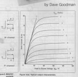
On another subject, from post 103 (thanks for the research and post RS232) is it just me, or are these Vgs labels backwards? .. or perhaps suffering some other indignity that I'm not smart enough to sort?
Cheers
Not to pick a fight, but I wouldn't call 3 to 6 times higher supply voltage, to be 'slightly higher'. The typical op-amp sports +/-15V rails; audio power amps are more likely to be +/-40 to 90V.
And maybe it's just me, but I think of 3 to 10 amps of output current to be more than just 'beefier', than 10 to 40 milliamps.
Then there's the availability of '+' and '-' inputs, and typically over 70dBV open loop gain.
But the 'real' difference, is that the term "op amp" has become widely-agreed-upon to refer to a Monolithic Integrated Circuit, with relatively high-impedance inverting and non-inverting inputs, and excellent PSRR, da da, da da ..
Not that there's anything much to be accomplished by my nit-picking .. But it does seem (to me, at least 😉) like agreed-upon terms save time and mental effort -- especially in a field with this much complexity. 😀
On another subject, from post 103 (thanks for the research and post RS232) is it just me, or are these Vgs labels backwards? .. or perhaps suffering some other indignity that I'm not smart enough to sort?
Cheers
Attachments
Last edited:
No, silly. I have power amps at work. They occupy multiple 19" racks, run at 22kV, and require a whole building full of chillers.
These little things are opamps. Just because we typically design the negative feedback network onto the PCB doesn't mean they don't have a negative input.
Think of it in dB terms. You can get perhaps 500mW out of a monolithic NE5532. Put a couple of dozen in parallel and you've got ~5W, or 10dB more. 50W is just another 10dB, and 500W is just 10dB on that.
And doesn't _everyone_ design their amps for >100dB open-loop gain, high PSRR, high input impedance and low offset?
OK, I'll happily concede your point concerning scale. Wouldn't mind a peek at those 19" racks -- or the electric bill! 😉 22kV, huh? Wonder how many folks herein are thinkin' in those scales, though ..
So .. I guess your hypothesis (if that's the right word 😱) is that a 20 or 30dB difference in power output doesn't deserve a different *classification*? .. or monolithic either?
Cheers
So .. I guess your hypothesis (if that's the right word 😱) is that a 20 or 30dB difference in power output doesn't deserve a different *classification*? .. or monolithic either?
Cheers
Last edited:
Actually speaking seriously my rationale is more around the design process. For me the design process for an opamp is exactly the same as that for an audio power amp. As I said before, I just use a slightly higher power supply voltage and more robust output devices. Everything else is the same from a design perspective - gain, offset, input impedance, CMRR, PSRR, noise, stability.
Thinking power amps are somehow special (or even worse, that you can skip things because the output is higher power) is not useful.
At my work I am lucky enough to have a pair of very large klystron microwave amplifiers (and a whole lot of smaller ones) that _are_ special. And incredibly cantankerous. Though I did diagnose in a tetrode-based HV power supply by modelling it in LTspice recently, so there's that.
Last edited:
Glad you picked that up vgs I scratched my head on that one. But did not say anything just in case I got it wrong just being a hobbyist so tend to tread with caution ha ha.
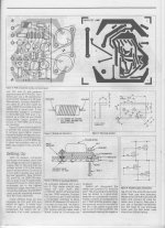
Forgot now setting up bias using this configuration you need to remove the inductor? Plus it uses the pins for measurements. Now those pins obviously don't tally with mine so anyone know what pins are for what think 1 -5 or 6. Obviously 2 go to the fuses. Where do the other two transformer leads go too on this one?
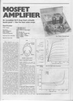
Found the article on the 100/150W amp (8/4 ohm) from maplin and like I said it's the same thing just higher power Mosfets (J50/K135 instead of J48/K133) and higher power rail +/-55 Vdc (+/-58vdc max)
To setup bias you don't need to remove anything from the board just to add the 100R before the fuse.
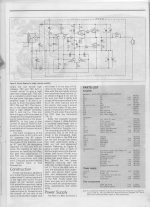
The numbering on the board is easy to follow it's just supply rails (+/-) input and output
1- Output
2 - + supply
3 - Input
4 - ground
5 - - supply
To setup bias you don't need to remove anything from the board just to add the 100R before the fuse.
The numbering on the board is easy to follow it's just supply rails (+/-) input and output
1- Output
2 - + supply
3 - Input
4 - ground
5 - - supply
Last edited:
Thanks much appreciated. I have 10 pins as opposed to only 5 on that module that's why I asked. Are the gate resistors for this one higher resistance rating. Mine are marked 470r but have 220r installed. Notice on fist example there only 100r.
Cheers Chris
Cheers Chris
Your module(s) are clearly marked so you shouldn't have any problem in compare the 2.
About the gate resistors, well I'm no expert (and someone will jump in soon) but it all depends on the design and voltage/current need to feed the Mosfet but on the Hitachi application note the 100W amp only has 100r and the 50W one none at all.
Hope someone jumps in to give a better explanation.
About the gate resistors, well I'm no expert (and someone will jump in soon) but it all depends on the design and voltage/current need to feed the Mosfet but on the Hitachi application note the 100W amp only has 100r and the 50W one none at all.
Hope someone jumps in to give a better explanation.
Attachments
Last edited:
Yeah not sure i need to mess around with the 100r resistors connected to fuses etc. Just want to set bias via the trimmer as that is all it will need. The other checks mentioned prior are more for if you are building from scratch. This is fully built so it's just getting the mA across fuses to around 100mA and the outputs between 0v and max 100mV. All I've changed is the trimmer. So for instance it says connect fuse 2 to pin 5 which is -ve supply etc etc all that's installed and soldered in so I just need to trim and measure across the fuses and +/- supplies. Its says 50mA but I'm sure this would be fine at 150mA. Plus it says rotate trimmer fully clockwise I would have though it would be full ccw highest resistance going to the mosfets.
If I go full cw then it will just be the gate resistors holding back the current. Unless I'm looking at my tracks on the pcb wrong.
If I go full cw then it will just be the gate resistors holding back the current. Unless I'm looking at my tracks on the pcb wrong.
No got that wrong full ccw will give me the full 1k of the trimmer on the BFs if I go fully cw then there will be 0R!
- Home
- Amplifiers
- Solid State
- BK Electronics mosFET 100 watt modules