Et Voila, basically my prototype circuit values: R7 140 Ohms, R8 5.8 Ohms, R9 1.07 Ohms, V Ref = 8.2 V (I actually have 9.1 V). V out is set to 20 V, V in is 25, primary current source is set to 160 mA, current draw of load is 100 mA.
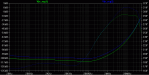
First output impedance, V1 (green) is with 5mA, V2 (blue) is with 10mA AC current in the load:
First output impedance, V1 (green) is with 5mA, V2 (blue) is with 10mA AC current in the load:
Attachments
Martin,
Looking really great. Lets wait Jan’s (and others) comment and see if we can move forward from this point.
Appreciate your excellent work and input on this reg.
Cheers,
Looking really great. Lets wait Jan’s (and others) comment and see if we can move forward from this point.
Appreciate your excellent work and input on this reg.
Cheers,
Martin, if I may ask, what led model are you using? Would it be possible to post it?
Also, in the Zout plot, could you please post V(out)/I(load) and then set to linear, so that it shows it in ohms?
Thank you in advance!
Also, in the Zout plot, could you please post V(out)/I(load) and then set to linear, so that it shows it in ohms?
Thank you in advance!

Looking good, Martin,
Could you do something for me while you've got it running so well - Will it still function with a load of 250mA @ 25volts with a shunt current of 100ma ( 40% of o/p)?
And could you also try out the original way of running the led current directly to groung instead of into the zener - just to confirm.
Many thanks for your efforts, especially as you are so short of time.
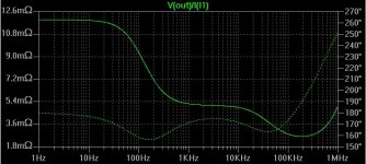
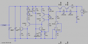
Martin, the output impedance in my simulation looks like the attached image.
The transfer function does correspond, IMHO, at about 12 mOhm.
--- Transfer Function ---
Transfer_function: 8.33249e-007 transfer
v1#Input_impedance: 14208.2 impedance
output_impedance_at_V(out): 0.0119379 impedance
The transfer function does correspond, IMHO, at about 12 mOhm.
--- Transfer Function ---
Transfer_function: 8.33249e-007 transfer
v1#Input_impedance: 14208.2 impedance
output_impedance_at_V(out): 0.0119379 impedance
Attachments
MRupp said:Now PSRR, V in 25V DC, 1 V AC, load 100 mA DC, no AC component:
Nice flat in the audio band. Lets see how it holds up on a real pcb 😉
Jan Didden
ikoflexer said:Martin, the output impedance in my simulation looks like the attached image.
The transfer function does correspond, IMHO, at about 12 mOhm.
--- Transfer Function ---
Transfer_function: 8.33249e-007 transfer
v1#Input_impedance: 14208.2 impedance
output_impedance_at_V(out): 0.0119379 impedance
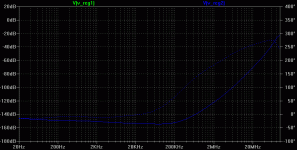
Maybe you can set your x scale to the same range as Martin's so it is better to compare, like 20Hz-20MHz.
I wonder what caused the rise at low frequencies? Did you use the circuit posted above?
Jan Didden
janneman said:
Maybe you can set your x scale to the same range as Martin's so it is better to compare, like 20Hz-20MHz.
I wonder what caused the rise at low frequencies? Did you use the circuit posted above?
Jan Didden
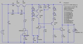
Here's with the x scale in that exact range. I will post the exact circuit next. I don't know why that rise.
Attachments
Hi,
can you confirm the values of r15 & r16 in the last two schematics?
15k or 1k5, 14k or 1k4 or 10k?
What does led2.1 mean? Is that a 2.1V Vf?
can you confirm the values of r15 & r16 in the last two schematics?
15k or 1k5, 14k or 1k4 or 10k?
What does led2.1 mean? Is that a 2.1V Vf?
AndrewT said:Hi,
can you confirm the values of r15 & r16 in the last two schematics?
15k or 1k5, 14k or 1k4 or 10k?
What does led2.1 mean? Is that a 2.1V Vf?
R15 = 1k5
R16 = 1k4
Indeed, 2.1V Vf, and the complete model for led2.1 is
*Typ RED,GREEN,YELLOW,AMBER GaAs LED: Vf=2.1V Vr=4V If=40mA trr=3uS
.MODEL LED2.1 D (IS=93.1P RS=42M N=4.61 BV=4 IBV=10U
+ CJO=2.97P VJ=.75 M=.333 TT=4.32U)
ikoflexer said:
Here's with the x scale in that exact range. I will post the exact circuit next. I don't know why that rise.
The rise looks like an almost perfect 6dB/oct so would point to an RC-time. But which one

Edit: But of course! R15/C5. Make C5 bigger and the rise will move to lower freqs.
BTW What's the purpose of R12?
Jan Didden
janneman said:
The rise looks like an almost perfect 6dB/oct so would point to an RC-time. But which one
Edit: But of course! R15/C5. Make C5 bigger and the rise will move to lower freqs.
BTW What's the purpose of R12?
Jan Didden
With C5 = 220uF the curve dips but not below 5mOhm. I wanted to simulate the exact circuit that Martin simulated, so I thought this was it. Should R12 be a different value? Or scrapped altogether?
If this is not it, please point me to the circuit that was discussed by Martin a few posts ago.

First answer - the others I will only get to in a while:
LED model, as per my document link in a previous post (still suggested read) - the standard model in LTSpice does not work properly:
.model LED_RED D(Is=5.5526E-15 Rs=2.2974 N=2.3299 CJO=2.97E-12 M=.3333 VJ=.75 BV=4 Ibv=10.000E-6 TT=4.3200E-6 mfg=NoName type=LED)
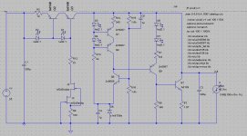
Also, in your diagram you have different component numbering than in the original circuit. Here is my sim circuit with the values I used in my prototype that I built, and hopefully I have the correct component numbering:
P.S. I am interested in how you calculate the performance (i.e. your sim statements), can you post / suggest? I only started playing with spice for this project and did not RTFM (this should spell "arr tee eff emm" but somehow it is censored) 😀
LED model, as per my document link in a previous post (still suggested read) - the standard model in LTSpice does not work properly:
.model LED_RED D(Is=5.5526E-15 Rs=2.2974 N=2.3299 CJO=2.97E-12 M=.3333 VJ=.75 BV=4 Ibv=10.000E-6 TT=4.3200E-6 mfg=NoName type=LED)
Also, in your diagram you have different component numbering than in the original circuit. Here is my sim circuit with the values I used in my prototype that I built, and hopefully I have the correct component numbering:
P.S. I am interested in how you calculate the performance (i.e. your sim statements), can you post / suggest? I only started playing with spice for this project and did not RTFM (this should spell "arr tee eff emm" but somehow it is censored) 😀
Attachments
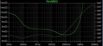
AndrewT said:and the impedance of zd6 with C4 (1uF) may be the other band limit.
Change both to 100uF.
I don't think C5 is that critical, I mean at low frequencies 10 or 12milliohms is fine as the load will have more PSRR than at higher freqs anyway.
C4 is interesting, 100uF across say 10 ohms dynamic impedance has a corner freq of about 1.5Hz. So, something in the order of a few 10's of uF might help.
I was just wondering about R12, hadn't noticed it before. I guess *someone* had a good reason to put it in?
Jan Didden
- Status
- Not open for further replies.
- Home
- Amplifiers
- Solid State
- Bipolar discrete shunt regulators