So what is the current status here? Are we waiting for a prototype to be made and tested before the group buy is restarted?
Thanks.
Thanks.
I've been catching up with a bunch of other stuff (including managing to blow out both of my Rotel RB850 amps today) and was planning on building this around mid-april when Mouser gets more BF245A in stock.
My 'playspace' has been turned upside down recently though as I desperately needed to organize the space and still need a cabinet and some drawer space.
Anyone else etched and/or stuffed one yet? No news?
Surely, the nice weather recently has reprioritized a few things for me
My 'playspace' has been turned upside down recently though as I desperately needed to organize the space and still need a cabinet and some drawer space.
Anyone else etched and/or stuffed one yet? No news?
Surely, the nice weather recently has reprioritized a few things for me
Sorry to hear about those Rotel amps… what were they driving?
Hope that soon we can have others, like you, interested on doing some work on this fine regulator, it would be a pity to see people loosing interest as Jan says.
Cheers,
Hope that soon we can have others, like you, interested on doing some work on this fine regulator, it would be a pity to see people loosing interest as Jan says.
Cheers,
Anyone else etched and/or stuffed one yet? No news?
Hmmm, not sure if this counts but I put the schematics in my layout software (Target) and recreated the board closely following the original arrangement. It is only single-sided so that it is easier to prototype and I also put in electrolytics for C1 and C3 (especially C3 needs to have a much higher value - 220 µF or better more). So far I have only etched one board but hope to stuff it during the next few days - IF wheather permits as it is improving over here too 😀
Hi Martin,
Ths is a rather different layout to Twitchie's excellent work - It is intended as an aid to testing and such with slightly more room for the components and thick tracks and donuts for multiple soldering and easier home etching.
I have used the component numbering and Cct as per post 282 and added the C1, 3, 4, options - the transistor Q1, 6, 7, have offset pins for simpler thick tracks. Tracks are 2.5mm, 1.5mm and some 50mil (1.27mm) Sorry the picture isn't very clear.
Attachments
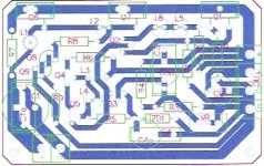
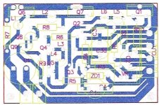
The previous pcb design is about 70 x 45mm - the one below is just on the 60 x 40mm size and it's getting pretty crowded but with the offset pins for the Q1, 6, & 7, it fits together fairly well.
Track sizes are: large 2.5mm, med 1.5, 1.25 (50 mil) and some thinner 30mil (0.75mm)
Track sizes are: large 2.5mm, med 1.5, 1.25 (50 mil) and some thinner 30mil (0.75mm)
Attachments
jameshillj said:... the transistor Q1, 6, 7, have offset pins for simpler thick tracks. Tracks are 2.5mm, 1.5mm and some 50mil (1.27mm)
Neat trick and very nice work James 😀
Anyone built anything yet?
@apassgear - my Rotel amps were driving my home theater subs and while swapping out the receiver, I managed to yank the sub leads loose (passive amp) so that they came into contact with each other w/o my knowledge. I figured the amp finally gave up after 25 years and wouldn't turn on, so I went to fetch the other one and killed that one too before I realized my mistake

Oh well, another pair of projects for me and a good excuse to finally replace the caps (or just gut them and build LM4780 amps in the cases)
Hi James,
very interesting layout. I also found that having some more space makes life easier when etching AND builing the circuit, my own incarnation is also ca. 70 x 40 mm. I found though that after placing the components on the board I can now better see where I need more or less space, and will need a slight redo.
After some stupid mistakes that cost me a number of extra hours I finally managed to get a regulator up and running (with my layout). The only thing I can connect it to right now is my turntable (electronic regulation, not directly to the motor) and it does work very well.
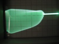
One "little" problem though, the regulator oscillates at 10 MHz. The oscillation is pretty stable and independant of the load. My components are: D14 = 9.1V Zener, C3 = 470µF/25V low impedance, C1 = 22µF/50V, R7 = 140 Ohms, "R8" = 3,3µH inductance (0.2 Ohms) Fres > 90 MHz. Attached is a screen shot, 0.5 µS/cm, 0.1V/cm. The oscillation shows stable bursts of 4µS every 8 µS, i.e. with ca. 4 µS "silence". To me this looks like there could be two resonant systems in the circuit that are coupled, just an idea. At any rate, I think that the error amp should not amplify at 10 MHz and we need to see how to resolve this. Suggestions anyone?
very interesting layout. I also found that having some more space makes life easier when etching AND builing the circuit, my own incarnation is also ca. 70 x 40 mm. I found though that after placing the components on the board I can now better see where I need more or less space, and will need a slight redo.
Anyone built anything yet?
After some stupid mistakes that cost me a number of extra hours I finally managed to get a regulator up and running (with my layout). The only thing I can connect it to right now is my turntable (electronic regulation, not directly to the motor) and it does work very well.
One "little" problem though, the regulator oscillates at 10 MHz. The oscillation is pretty stable and independant of the load. My components are: D14 = 9.1V Zener, C3 = 470µF/25V low impedance, C1 = 22µF/50V, R7 = 140 Ohms, "R8" = 3,3µH inductance (0.2 Ohms) Fres > 90 MHz. Attached is a screen shot, 0.5 µS/cm, 0.1V/cm. The oscillation shows stable bursts of 4µS every 8 µS, i.e. with ca. 4 µS "silence". To me this looks like there could be two resonant systems in the circuit that are coupled, just an idea. At any rate, I think that the error amp should not amplify at 10 MHz and we need to see how to resolve this. Suggestions anyone?
Attachments
Martin,
I've sort of lost track of what is now the 'official' circuit diagram for your board - can you please post it?
Jan Didden
I've sort of lost track of what is now the 'official' circuit diagram for your board - can you please post it?
Jan Didden
Jan,
Understandable, given the numerous schematics. I was referring to the last version from twitchie in post 322: http://www.diyaudio.com/forums/showthread.php?postid=1781078#post1781078
Understandable, given the numerous schematics. I was referring to the last version from twitchie in post 322: http://www.diyaudio.com/forums/showthread.php?postid=1781078#post1781078
Martin,
What you see in the burst is most probably that it starts to oscillate, which shifts some internal operating point which kills the oscillation, the operation point shifts back, it starts again etc. Probably just on the verge of oscillation.
Some ideas: I'm not entirely sure what that 3.3uH does, I understand the rationale to decrease loop gain with freq increase but an emitter follower also become inductive with phase shifts at higher freq and I'm not sure what the combination does.
Things you could try: replace R8 by a real resistor of like 5 ohms, or increase R9 to 2 or 3 ohms.
Did you check the DC voltages internally that they are as expected?
Jan Didden
Jan,
Thanks for the hints, I did check the DC values but not systematically and will redo it again, probably this evening. The idea with R8 was indeed to reduce loop gain. I will see that I replace some components as you suggested, I am thinking of soldering in some DIL IC sockets (or whatever you call them) that allow to "plug" in the resistors.
P.S. Any other place to reduce loop gain at high frequencies, esp. around Q3 ?
I can't find the 3u3H that Janneman refers to.
Which schematic are you using?
Is the shunt CCS feeding the LED current into the top of the Zener reference? I don't care for this stupid way of doing it, no matter what the simulator says.
Which schematic are you using?
Is the shunt CCS feeding the LED current into the top of the Zener reference? I don't care for this stupid way of doing it, no matter what the simulator says.
Andrew,
The idea was to make the ref zener current less variable with the transistor current driving it and thus making the ref more stable. You think that won't help?
Jan Didden
The idea was to make the ref zener current less variable with the transistor current driving it and thus making the ref more stable. You think that won't help?
Jan Didden
Jan, think it through.janneman said:Andrew,
The idea was to make the ref zener current less variable with the transistor current driving it and thus making the ref more stable. You think that won't help?
Jan Didden
twitchie said:I've been catching up with a bunch of other stuff (including managing to blow out both of my Rotel RB850 amps today) and was planning on building this around mid-april when Mouser gets more BF245A in stock.
My 'playspace' has been turned upside down recently though as I desperately needed to organize the space and still need a cabinet and some drawer space.
Anyone else etched and/or stuffed one yet? No news?
Surely, the nice weather recently has reprioritized a few things for me
twitchie, two local shops have the bf245a in stock: Creatron at College & Spadina, and Honson (inside the Home hardware store) a bit West of Spadina, on the North side of College. The Honson store is also good for getting cheap bd140 and 139.
i've seen so many version of this reg. psu?
where is the original (last version) schematic?
Regards
La Ode
where is the original (last version) schematic?
Regards
La Ode
crt said:i've seen so many version of this reg. psu?
where is the original (last version) schematic?
Regards
La Ode
2nd post page 13
replace R8 by a real resistor of like 5 ohms, or increase R9 to 2 or 3 ohms.
Jan,
as you suggested, the 3,3µH inductor caused the problem (if I had looked at the simulation, even considering their limitations, I would have noticed that the phase of Vout crosses 360° at 10 MHz, I presume that is a hint?).
Increasing R9 from 1 to 6 Ohms did not change the oscillation, but replacing R8 with a 6 Ohm resistor (R9 = 1 Ohm) stopped it. Now I just see some HF above the noise floor at 5 mV/cm. This is under no load but I presume a normal load will not change this. Btw., Vbe of T2 was measuring 330 mV with the oscilations, now it is 640mV.
- Status
- Not open for further replies.
- Home
- Amplifiers
- Solid State
- Bipolar discrete shunt regulators