If I'm looking at this correctly the LED string loops back on its self? It starts and ends on output 1

with the 9.1v zeners standing in for the LM4040, it holds steady at 12.06v but only led3 is light - 1 and 2 are still dark
Latest modification - I fixed the routing from LED3 to Out and managed to get rid of a jumper (down to 2 now). I opened up the spacing a bit to make it easier to etch, added pads on the holes and smoothed out some of the lines.
Oh yeah, I also arbitrarily put a pot overlayed onto R8 - I have no clue how this circuit works, but just making a SWAG that R8 determines something worth making it adjustable.
Anyway, if anyone wants to take a crack at this, I'm uploading my Eagle .brd file.
Here's the current incarnation:
Oh yeah, I also arbitrarily put a pot overlayed onto R8 - I have no clue how this circuit works, but just making a SWAG that R8 determines something worth making it adjustable.
Anyway, if anyone wants to take a crack at this, I'm uploading my Eagle .brd file.
Here's the current incarnation:
An externally hosted image should be here but it was not working when we last tested it.
Attachments
That’s a very nice layout, again and thanks for posting the file.
Anyone willing to test drive this new incarnation?
🙂
Anyone willing to test drive this new incarnation?
🙂
twitchie said:Anyway, if anyone wants to take a crack at this, I'm uploading my Eagle .brd file.
Hi twitchie,
Is the schematic available, I don't trust PCBs without the schematic.
regards
Babowana said:. . . ???
See the post #220 . . .
>🙂<
That's not the schematic twitchie generated his PCB from. The best way to check if the logic of a PCB is correct, is to check the schematic it was generated from.
regards
You just beat me to this. If you guys are serious about this, you draw the circuit in Eagle which then *guarantees* that the board is exactly like the circuit. When you build the layout, Eagle will list the components in your circuit, show you the required connections (called the 'ratsnest') and will even tell you when you make an eror.
Beats attacking a fresh virgin pcb with the old Exacto knife any day.😉
Jan Didden
Beats attacking a fresh virgin pcb with the old Exacto knife any day.😉
Jan Didden
janneman said:
Beats attacking a fresh virgin pcb with the old Exacto knife any day.😉
Amen to that

... although there is some dark satisfaction in attacking a pcb when it doesn't quite work

Sorry gents, I don't have a corresponding .sch file ... if I get time to figure out how to import/find the LM4040 ... maybe ... but until then, I've burned through too much to continue on blindly like this w/o some advice ...
I'm trying to help where I can, but I'm at a total loss trying to figure out why it's not quite working. I'm pretty sure the layout is correct (didn't I already eat those words?
 ...
...  )
)Has anybody sim'ed this to confirm it's correct?
Lastly, does anyone have anything to say about the variant of LM4040 to use or should we just use a zener (and if so, what value?)
For me the only reason to go for an LM4040 would be if it had lower noise than a zener. I don't know if this is true; I do know that the LM4040 is not specifically low noise.
But first step now should be to have the circuit in Eagle so that the pcb will be without errors, guaranteed.
Jan Didden
But first step now should be to have the circuit in Eagle so that the pcb will be without errors, guaranteed.
Jan Didden
janneman said:For me the only reason to go for an LM4040 would be if it had lower noise than a zener. I don't know if this is true; I do know that the LM4040 is not specifically low noise.
But first step now should be to have the circuit in Eagle so that the pcb will be without errors, guaranteed.
Jan Didden
... and not particularly cheap either
I was always working under the assumption that Colin's version would be the one going into production, so let's wait to hear from him since his will have been generated from his schematic.
Jung-Self CCS
I find it strange that we are not using the results of Jung's investigations here. In particular, the topology he investigated that was based on a CCS of Doug Self's design, which Walt reporte on in a letter to AudioXpress a few years ago.
Given the performance of this circuit ( it challenged the measurement capabilities of Walt's AP1 ), its elegance, and simplicity, I see little reason to use any other CCS.
I've attached a circuit diagram.
Attachments
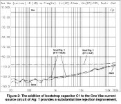
Jung-Self CCS Performance
I thought some o you may be interested in the measured performance of the "Jung-Self" CCS above. I've attached a picture of Walt's results. As you can see, it's so close to the measurement limit of the AP1 one wonders if the difference is simply inherent measurement error between the two measurements he made.
The reprint of the original is available on Walt's site here:
http://www.waltjung.org/PDFs/AX_Letters_0907.pdf
Attachments
Re: Jung-Self CCS Performance
The same improvement can be made by replacing the two resistors with a CS.
It's a nice circuit, that's true. As there are many nice circuits 😉
Jan Didden
asibbald said:I thought some o you may be interested in the measured performance of the "Jung-Self" CCS above. I've attached a picture of Walt's results. As you can see, it's so close to the measurement limit of the AP1 one wonders if the difference is simply inherent measurement error between the two measurements he made.
The reprint of the original is available on Walt's site here:
http://www.waltjung.org/PDFs/AX_Letters_0907.pdf
The same improvement can be made by replacing the two resistors with a CS.
It's a nice circuit, that's true. As there are many nice circuits 😉
Jan Didden
Now, to close the loop, if Twitchie would get your schematic file and transfer that to the board part, Eagle should show no errors and all connections routed, right? (Assuming you guys used the same parts reference numbers).
That'll then give us a schematic and board that are identical and can be the basis for the building.
Jan Didden
That'll then give us a schematic and board that are identical and can be the basis for the building.
Jan Didden
janneman said:For me the only reason to go for an LM4040 would be if it had lower noise than a zener. I don't know if this is true; I do know that the LM4040 is not specifically low noise.
But first step now should be to have the circuit in Eagle so that the pcb will be without errors, guaranteed.
Jan Didden
I will try with LM329, which has lower noise than LM4040.
Sajti
janneman said:Now, to close the loop, if Twitchie would get your schematic file and transfer that to the board part, Eagle should show no errors and all connections routed, right? (Assuming you guys used the same parts reference numbers).
Hi Jan,
Unfortunately it is not that easy.
 I started to do it but it was going to take some time and there would be no guarantee that in the end it would be OK. It would be quicker for me to start again from scratch.
The component values, although they appear the same on the images, are actually different. Different versions of Eagle were used and my component libraries are all custom.
BTW: cetools had an Eagle schematic and PCB in post #220 that I assume should be the "real" project files.
regards
Getting there slowly:
An externally hosted image should be here but it was not working when we last tested it.
- Status
- Not open for further replies.
- Home
- Amplifiers
- Solid State
- Bipolar discrete shunt regulators