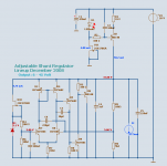
I have been playing around with regulators in LTSpice, trying to come up with something I like for use with a DAC I am working on. The regulators shown are what I am currently intending to use to power the discrete I/V and output buffer stage. I will also most likely adapt this for powering the 3.3v and 5v digital supplies.
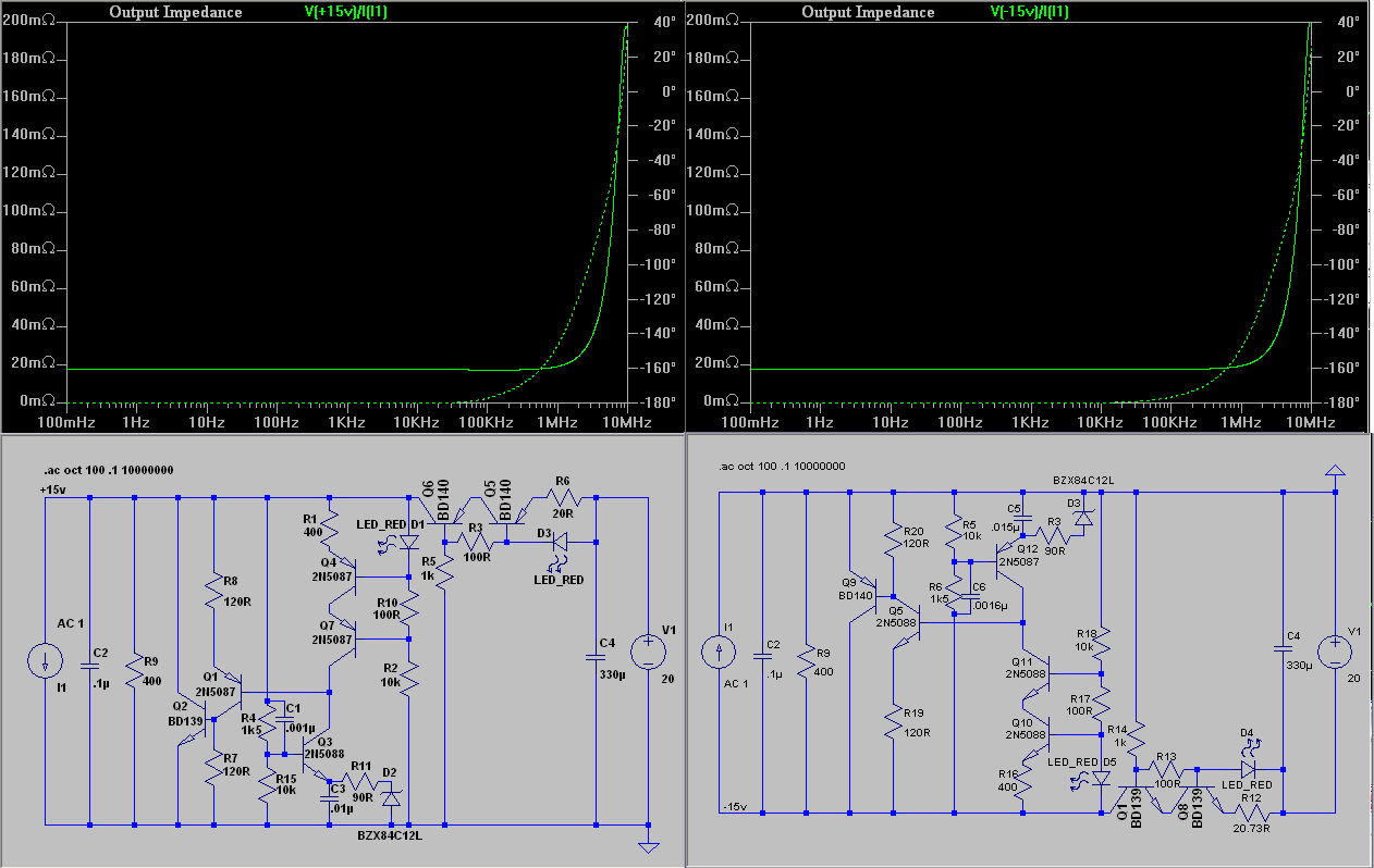
I/V topology it is intended for is folded cascode class A, so has constant power draw, and requires +/-15vdc rails between 40-50mA per channel, depending on the variation I use. I prefer, at least conceptually, to use shunt regulators when possible, so worked on coming up with some possibilities. The one below is what I think I am going to go with. Not the absolute best performance possible, but I think it should be more than sufficient for my needs.
The minor parts variations between the two circuits, besides those obviously directly caused by changing polarity, are to balance performance. It seems the only truly important parts are the two compensation capacitor values. Hopefully my old *** 20MHz DSO will be up to the task of finding real world values. Of the various transistor models I tried, it is ironic that the best performance seems to come from the ones I have most of in my parts bin.
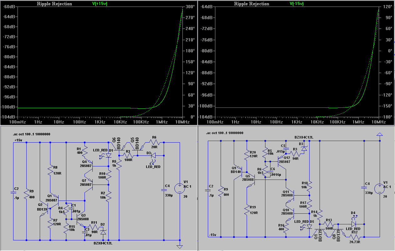
Rising impedance at HF can be tamed with ~6.8uf of capacitance on the output, though you have to be careful with the ESR of the capacitor. Reduction in ripple rejection at HF can most easily be tamed by a small CLC filter before the regulator. A 1uf, 1uh 1ohm, 1uf pi filter knocks the heck out of the noise at HF, rolling it off past about 10KHz.
Remember that all of these values are simulator values, and my skill with simulation is sorely lacking, so take everything here with a shaker of salt.
I/V topology it is intended for is folded cascode class A, so has constant power draw, and requires +/-15vdc rails between 40-50mA per channel, depending on the variation I use. I prefer, at least conceptually, to use shunt regulators when possible, so worked on coming up with some possibilities. The one below is what I think I am going to go with. Not the absolute best performance possible, but I think it should be more than sufficient for my needs.
The minor parts variations between the two circuits, besides those obviously directly caused by changing polarity, are to balance performance. It seems the only truly important parts are the two compensation capacitor values. Hopefully my old *** 20MHz DSO will be up to the task of finding real world values. Of the various transistor models I tried, it is ironic that the best performance seems to come from the ones I have most of in my parts bin.
Rising impedance at HF can be tamed with ~6.8uf of capacitance on the output, though you have to be careful with the ESR of the capacitor. Reduction in ripple rejection at HF can most easily be tamed by a small CLC filter before the regulator. A 1uf, 1uh 1ohm, 1uf pi filter knocks the heck out of the noise at HF, rolling it off past about 10KHz.
Remember that all of these values are simulator values, and my skill with simulation is sorely lacking, so take everything here with a shaker of salt.
Nice circuits. Did you play with the an increased value for C1, and/or increasing R7? I think there is some potential to get the Zout closer to good integrated circuit series regs, which routinely go below 1mOhm.
Jan Didden
Jan Didden
Jan, what will increasing C1 do? It looks like the divider is only losing about a dB at AC anyway.
Jan,
Yes, I have played around with both values. Increasing C1 (and/or C3) just reduces HF impedance, causing a dip before the spike. I chose the values I did for maximal flatness of impedance, though in reality when building it, I probably will use larger values than this just because of my lack of measuring equipment making tuning values difficult. I also didnt find any better values for R7 than shown. Actually, with regards to impedance, the most improvement to be had that I have found thus far is at the voltage reference. That RC filter is significantly increasing the output impedance. Shorting it out and readjusting the compensation caps drops regulator output impedance down to about 8mohm up to several hundred khz.
By good integrated circuit series regs, do you mean 3 terminal ones, or opamp based designs like the one by Walt Jung and yourself? What measurements I have seen of regs like LM317 (yeah, I know you said good regs) says that it's impedance isnt a heck of a lot lower (~10mohm), and then only at low frequencies, and then only by the grace of large compensation capacitors. I can get that kind of effect here by greatly increasing C1 and C3. 1000uf for C1, C2, and C3 gives 2.5mohm for all frequencies above 10hz, though C2 must be low ESR. LF impedance is still dependent on the regulator though.
The reason for this regulator at all is because I had been planning to use the TL431, but when I started really looking at it's performance, I didnt really like what I saw. This was something simple I came up with to significantly improve on the performance, while still being very inexpensive to build. I also wanted something that wasnt dependent on huge capacitors for it's performance. It seems to me that series regs have a bit easier time getting the real low output impedance than shunt since they almost always have much more current through them. Doing nothing but dropping R6 to 15ohm more than halves this regulator's output impedance, by increasing the current through it.
SY said:Jan, what will increasing C1 do? It looks like the divider is only losing about a dB at AC anyway.
Yeah that's true, it's limited in its effect because of the resistance ratio to R15.
On the other hand, increasing R7 would increase the loop gain and that lowers Zout almost at the same ratio.
Jan Didden
cetoole said:Jan,
[snip] I also didnt find any better values for R7 than shown. Actually, with regards to impedance, the most improvement to be had that I have found thus far is at the voltage reference. That RC filter is significantly increasing the output impedance. Shorting it out and readjusting the compensation caps drops regulator output impedance down to about 8mohm up to several hundred khz.[snip]
Well, your circuit is pretty good as it is, but I've been working on supplies so long I can't resist to comment on them 😉
I would expect a halving of the Zout when you double R7.
The filter impact is clear: that 90 ohms is directly in series with the reference, seen from the emitter. So, when the emitter current varies (which it will when the input voltage / ripple varies), the reference is also directly varying. I would just delete the resistor but keep the capacitor (in parallel with the ref diode), but make it an electrolytic of a few tens of uF.
Better yet, replace that zener diode with a good low impedance reference diode. Maybe one of those TL431's you have left, the're better than zeners. You can use a 5V ref one if you adjust the feedback ratio resistance.
OTOH, you probably are getting close to dinimishing returns now, as the impedance of the connection from the supply output to the load circuits may have a similar value to your Zout.
If you remember, we went to remote sensing to get around that.
Jan Didden
Hi Cetoole,
Just read through this thread.......looks like a well thought through design.........any news how the regulators sound in real life ?
mike
Just read through this thread.......looks like a well thought through design.........any news how the regulators sound in real life ?
mike
I suspect this topology offers more scope to achieve these impressive results for output impedance & bandwidth of output impedance.
Also a little thermal drift is not a big issue - at least in my book - when designing a 15V power supply.
Also a little thermal drift is not a big issue - at least in my book - when designing a 15V power supply.
Differential can give (much) lower output impedance, *but* the flatness of impedance, spikelessness over frequency (what a word) and ripple rejection are quite cool for such a 'economical' circuit.
I will definitly try it!
Rüdiger
I will definitly try it!
Rüdiger
I couldn't resist to play a bit with your circuit. When I replaced R7 with an active load (degenerated FET) and Q2 with an mosfet, the circuit simmed -30dB plus far into the Mhz-region.
I used slightly different ciruit values, though.
Rüdiger
I used slightly different ciruit values, though.
Rüdiger
Hi On,Onvinyl said:... When I replaced R7 with an active load (degenerated FET) and Q2 with an mosfet, the circuit simmed -30dB plus far into the MHz-region.
I used slightly different circuit values,
could you list your component values?
As a long time fan of current sourced shunt regs, I can only support this design project. Not quite the way I'd do it, but if you haven't listened to it yet, you are all in for a big HAPPY surprise.
WE use CCS'd shunt regs in all of our products, tube or SS, and could not get the sonic results we get without them.
The only suggestion I have for the circuit is to include a very small R in the shunt transistor to gnd, as a shunt current monitor. Otherwise it's very hard to tell if it's working correctly.
Regards, Allen
Am i the only one who's frightened by going directly from simulation into group buys?
Low output impedance and good bandwidth are certainly nice to have although i would love to have some real noise measurements and most importantly output waveform under pulsed load.
If someone does a subjective comparison to a nice Jung design would be even better.
Low output impedance and good bandwidth are certainly nice to have although i would love to have some real noise measurements and most importantly output waveform under pulsed load.
If someone does a subjective comparison to a nice Jung design would be even better.
No really,
but for approx. 5 Bucks.......its a bargain........to be honest I never was disappointed by Group Buys on DIYaudio.com!
🙂
Alan
but for approx. 5 Bucks.......its a bargain........to be honest I never was disappointed by Group Buys on DIYaudio.com!
🙂
Alan
Hello 🙂
I have done some shuntregulators to see what can be done.
I too, use a CCS 50 mA and a load 400 Ohm.
Input voltage/output voltage is also same as cetoole used in his first post.
In 20V out 15V
I use as reference Zener 5V1 with 5mA JFET CCS for minimum temp coefficient.
The shunt regulator is one dual differential BC550C driving current sinking transistors.
Comparing the output sense to the filtered Zener reference.
Question:
I use 100mV 100Hz ripple source overlayed on the 20VDC supply.
Is it okay use BODE Plotter 10Hz - 10MHz to compare the line ripple
with the ripple found on the 15.00 V output.
And this way estimate PSRR.
DVBjunky said:
but for approx. 5 Bucks.......its a bargain
Sure. If not counting my time and potentially dashed expectations 🙂
cetoole said:I have been playing around with regulators in LTSpice,
trying to come up with something I like ....
cetoole
I suggest this one.
The conditions are the same, 20Vin, 15Vout 50mA supply, 37.5mA load.
I did get one value of 9 milliOhm output impedance. I am not sure I did test correctly
Ripple rejection should be very high. My tests shows >=120 dB
Could you please setup my circuit and do the same nice test,
like you did in your first post.
Would be interesting to compare. Wouldn't it 😉
Regards
-----------------
PS. I told in prev post, I use 5.1 Volt Zener for temp stability.
Attachments
- Status
- Not open for further replies.
- Home
- Amplifiers
- Solid State
- Bipolar discrete shunt regulators