Dear Hennady,It will be possible to come up with a solution based on the topology of the Furious amplifier, modify the output stage and get rid of the power supply stabilizer. I’m just not sure that the design will be quick.
Please come up with an all BJT solution except that the Outputs to be Laterals!
-- Sarma.
Dear Wahab,
For single driver Full range loudspeaker systems, the sweet spot is around 30 to 50 watts. 63 volt electrolytics are very easy to get. So, a single power supply of nominal ~50 volts, with Elec cap output will fill the place, provided the quality is good. So around 10 years back, I first posted "Bigun's TGM8 with single Supply". This type of retro design with readily available components also avoids output dc protection complications, if the switch ON transients can be avoided.
I am also using this thread to learn more about amplifiers and compensation niceties.
Thank you for your interest and contributions.
--Sarma.
Please...Dear Hennady,
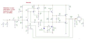
Please come up with an all BJT solution except that the Outputs to be Laterals!
-- Sarma.
Attachments

Dear Hennady,
Will it be possible to change M1 - IRF510 to a BJT please? How much is the current of the CCS?
Will it be possible to change M1 - IRF510 to a BJT please? How much is the current of the CCS?
If you use a bipolar transistor there, it will affect the thermal stability because... The bipolar transistor in the current generator has a negative temperature gradient. Side transistors have their own thermal stability, so their gradient does not add up and does not affect the temperature characteristics; I am using IRF in a power current generator.Will it be possible to change M1 - IRF510 to a BJT please? How much is the current of the CCS?
Dear Wahab,
For single driver Full range loudspeaker systems, the sweet spot is around 30 to 50 watts. 63 volt electrolytics are very easy to get. So, a single power supply of nominal ~50 volts, with Elec cap output will fill the place, provided the quality is good. So around 10 years back, I first posted "Bigun's TGM8 with single Supply". This type of retro design with readily available components also avoids output dc protection complications, if the switch ON transients can be avoided.
I am also using this thread to learn more about amplifiers and compensation niceties.
Thank you for your interest and contributions.
--Sarma.
Ok, that s quite high powers here, if you want 30W this require about 50V sustained supply and a 43V AC transformer, when idling there will be about 60V, so that s a little too much for a 63V capacitor, personaly i did settle for lower powers in the 15-20W range for my everyday lateral FETs amp.
Also laterals require about 100mA bias for best perfs although lower values works as well, at 100mA that make roughly 10W idle power for two channels, better to use a toroidal transformer since its losses are much lower than a classical E or double C transformer, i use a 30V transformer and laterals are biaised at about 20-25mA.
Anyway good luck with your project, i ll take a look from time to time to see in which direction the ship is sailing.
Member
Joined 2009
Paid Member
Given that perceived loudness doesn’t change much between 20W and 30W, perhaps it makes sense to size the amp for the use of 63V caps and convenient power transformer voltages.
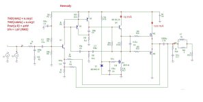
Yes, you are absolutely right, so I wrote down the initial currents of the Driver and Output stage, see attachmentAlso laterals require about 100mA bias for best perfs although lower values works as well,
Attachments


This is because of the driver, the output transistors in your model are most likely higher frequency than mine.The Gang amp as published in #43 has been entered into LTspice. There is heavy oscillation in the lower half of waveform.
Remove it from the C8 model, maybe this is the reason.
P-channel and N-channel laterals differ markedly in capacitance, with P-channel 50% more or so, although C9 should common them up at AC and hide this from the rest of the circuit - transconductance may differ a little too - so it is to be expected to see one device oscillate first if stability is borderline. That suggests it shouldn't take much change to stabilize it. Or one of the FET models is just wrong(!)
Fets capacitances difference is not the culprit, all the NFB around the VAS enclose the output stage, there s about nothing that
is enclosed locally through C7, you could as well remove it, and going to 120R from 100R for R12 is just cosmetic, i made a lot
of sims for this kind of compensation, what you see in the simulator for global frequency and phase response is not the real thing.
is enclosed locally through C7, you could as well remove it, and going to 120R from 100R for R12 is just cosmetic, i made a lot
of sims for this kind of compensation, what you see in the simulator for global frequency and phase response is not the real thing.
I found a solution, you need to connect R12 (see attachment.) to the output of the amplifier and recalculate the values of the correction capacitors, see attachment.The Gang amp as published in #43 has been entered into LTspice. There is heavy oscillation in the lower half of waveform.
Try making these changes, the amplifier quality parameters remain the same.
Attachments
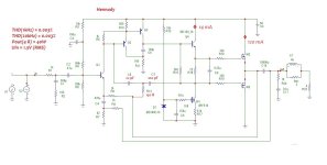

We see that the generation at the lower half-wave has become noticeably less, therefore the point is precisely in this correction circuit, namely in the choice of correction frequency. It is necessary to select (adjust) the capacitance ratings for your version of the transistor model.After the mod as in #56, the freq of oscillation changed.
Try increasing the 22pF capacitance to 47pF, and decreasing the 100pF capacitance to 47pF. My model shows an open loop gain of 106 dB, this is a large gain, and the unity gain frequency must be lower than the cutoff frequency of the output transistors. Because We have different models of output transistors, then such generation does not occur for me, and it is difficult for me to suggest a minimum value for these capacitors.
Dear all,
I took time to try following my earlier procedure. Disconnected the TMC, adjusted C5 for good olg margins. Added TMC with C7 = 680p and R12 = 1k5. Adjusted the currents in outputs. The oscillation is gone. The simulation is to be checked with TMC terminated at various points. The files are attached below.
Over load recovery is not good.
- Home
- Amplifiers
- Solid State
- "Bigun's TGM8 with single Supply" Revisited