It's easier for me to count in my head)). In the starting scheme at a frequency of 1 kHz, the gain of the input transistor is 35 dB. The linearity of this stage is +/-3.5 dB, which is generally not bad.
What you then got with the additions through the correction circuits in the feedback also needs to be taken into account.
Well, in the starting circuit it was not possible to create a 2nd order frequency correction, because... the frequency of the unity gain turns out to be more than 10 MHz .. ..
What you then got with the additions through the correction circuits in the feedback also needs to be taken into account.
Well, in the starting circuit it was not possible to create a 2nd order frequency correction, because... the frequency of the unity gain turns out to be more than 10 MHz .. ..
Last edited:

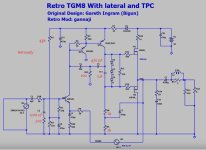
I can congratulate the scheme, it turned out very good. If we compare, for example, the John Linsey Hood scheme in class A, which is widespread in amateur circles, then I called your option more preferable. But the frequency correction needs to be improved.
Here is a fix, see attachment - marked in red. And yes, the slew rate of the signal will naturally be lower, but it does not have to be so high. The initial current of the output transistors was 350mA.
Linearity in the direction of audio frequencies before feedback, which I would call absolute, is less than +/-0.01 dB.
C11 was reduced to 1 µF because its task is to reduce the noise of biased diodes at high frequencies, and there the 10 µF rating is very large.
Linearity in the direction of audio frequencies before feedback, which I would call absolute, is less than +/-0.01 dB.
C11 was reduced to 1 µF because its task is to reduce the noise of biased diodes at high frequencies, and there the 10 µF rating is very large.
Attachments
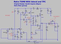
1200 pF - high frequency cutoff frequency is 294 kHzC2 is 1200uF ??
Of course, I think so too...))) there is a mistake in the picture... Thanks, fixed it.I think you meant pF
I checked the Thiel chain calculation - it was calculated correctly!
Attachments
Last edited:
I checked the Thiel chain calculation - it was calculated correctly!
Hennady, how should it be calculated? What is the formula?
This is the usual Boucher equation, which is compiled as a system with a load for a cutoff frequency of 20 kHz. This equation considers 2 chains L/R and R*C. So we look at the system from the output side of the amplifier, then we get a system of variable states for 4 variables, namely, a phase shift is added at a frequency of 20 kHz, which for L/R is defined as the arctangent (R divided by the angular frequency multiplied by L) and also the phase shift of the amplifier is added after correction at the same frequency. Practically, as a basis, I take the value of the phase shift for this circuit as 87.84 degrees, thanks to Douglas Self, he found this value empirically, then I can either make it a few degrees less or more, in this topic the value of the phase shift is 84.73 degrees , this is less than we wanted, but at the output there are laterals with a high output impedance, so this value is sufficient for a stable transient response.Hennady, how should it be calculated? What is the formula?
P.S. For more detailed information, you can defend your thesis))))
Last edited:
After incorporating the mods suggested by Hennedy, the OLG graph is as follows:


Attachments
Last edited:
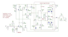
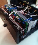
Here I added my own output stage using mosfets and bipolar power supply, as well as an input stage with increased overload capacity.
The result is a circuit with an absolutely linear frequency response before being covered by negative feedback.
The feedback depth is constant (20Hz-20kHz) and amounts to 70dB.
The output stage is proven stable on a simple and accessible element base. Bipolar power supply.
The result is a circuit with an absolutely linear frequency response before being covered by negative feedback.
The feedback depth is constant (20Hz-20kHz) and amounts to 70dB.
The output stage is proven stable on a simple and accessible element base. Bipolar power supply.
Attachments
Member
Joined 2009
Paid Member
Dear Hennady,
Please see https://www.diyaudio.com/community/threads/domestic-amplifier-furious.311083/post-5156783
I still feel that for power outputs below ~30 watts, a retro design with single power supply and output Elec cap is more appropriate, which was my original target.
Can I request you to kindly post a variant of your circuit with single supply, retaining input stage, vas stage and emitter follower buffer with Lateral outputs? Without too much compromise in quality?
Does the emitter follower buffer require 47 ma current? Please help me understand!
--Sarma.
Oh, you found a very specific project of mine for a radio amateur who thought that general feedback was bad. This amplifier worked with a headphone preamp and had a low output impedance, so I used mosfets to increase the input overload capability. However, later I made a project where the feedback also covered the output capacitor, while I was assembling it there were a lot of skeptics, after assembly it simply surpassed the JLH in quality. And what other projects with tubes at the input and others, there were many amplifiers of different projects, as a result the Fury project appeared, which finally demonstrated the need to use negative feedback in sound amplifiers, even from capacitors at the output.Please see https://www.diyaudio.com/community/threads/domestic-amplifier-furious.311083/post-5156783
I still feel that for power outputs below ~30 watts, a retro design with single power supply and output Elec cap is more appropriate, which was my original target.
Attachments
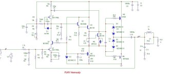
Such a high current for the emitter follower driver is needed to drive vertical mosfets.Does the emitter follower buffer require 47 ma current? Please help me understand!
Dear Hennady,
How about pulling that trick again, except that this time, only BJTs except for Outputs, which are to be Laterals ?
--Sarma.
How about pulling that trick again, except that this time, only BJTs except for Outputs, which are to be Laterals ?
--Sarma.
It will be possible to come up with a solution based on the topology of the Furious amplifier, modify the output stage and get rid of the power supply stabilizer. I’m just not sure that the design will be quick.Dear Hennady,
How about pulling that trick again, except that this time, only BJTs except for Outputs, which are to be Laterals ?
--Sarma.
R6 and R20 set the gain.
Q2 is not required.
47k input resistance can be 20k.
I used the 5th transistor as a constant current source instead of the bootstrap.
This was the car amp I built in 1988 using IRF530,9530 mosfets.
I also added an op amp for dc offset split supply use.
Q2 is not required.
47k input resistance can be 20k.
I used the 5th transistor as a constant current source instead of the bootstrap.
This was the car amp I built in 1988 using IRF530,9530 mosfets.
I also added an op amp for dc offset split supply use.
Sorry, I don’t quite understand what circuit your comment is for?R6 and R20 set the gain.
Q2 is not required.
47k input resistance can be 20k.
Dear Hennady,
Please see https://www.diyaudio.com/community/threads/domestic-amplifier-furious.311083/post-5156783
I still feel that for power outputs below ~30 watts, a retro design with single power supply and output Elec cap is more appropriate, which was my original target.
What is exactly the required output power.?
- Home
- Amplifiers
- Solid State
- "Bigun's TGM8 with single Supply" Revisited