
Before attempting to swap the 1k2 resistor I thought I would try a different 6n2p valve and now have the following readings:-
pins 1 & 6 pins 3 & 8
V1 88 87.4 2.1 2.1
V2 118 118 0.8 0.8
V3 211 212 123.5 123.5
These appear to be within the 10% as mentioned by Bas am I good to go?
Also the outputs are fluctuating by several milli volts am I right in assuming that these will drop when the output is loaded by having a linestage connected?
tia.
That sounds better, your HT is a little low but connect it up and see how it sounds.
Not from personal experience. But the Tungsram are highly rated...Phillips not too bad either. (Not too sure how reliable these reports were as they were from a seller)Any recommended brands of valves that work well with this.
Looks good!Got quite a lot done today , now for a curry
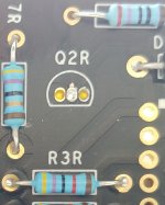
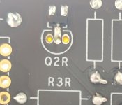
While I was soldering the JFET to Q2R, some solder went to the 3 little holes and now they are not separated anymore. Will this cause trouble? I tried to get solder out of it but the connection between the holes is still there, when measuring with ohmmeter. Comparing to the other side (Q2L), there is no connection.
Attachments
Yes, you need to get that solder out.While I was soldering the JFET to Q2R, some solder went to the 3 little holes and now they are not separated anymore. Will this cause trouble? I tried to get solder out of it but the connection between the holes is still there, when measuring with ohmmeter. Comparing to the other side (Q2L), there is no connection.
I did the same but managed to clear it with a solder sucker. You could alternatively try solder wick.
On a happier note I have music; not a proper listen just side one of Queen The Game. Proper listen over the next couple of days.
Thanks Alan; Oliver and Craig for doing this
On a happier note I have music; not a proper listen just side one of Queen The Game. Proper listen over the next couple of days.
Thanks Alan; Oliver and Craig for doing this
While I was soldering the JFET to Q2R, some solder went to the 3 little holes and now they are not separated anymore. Will this cause trouble? I tried to get solder out of it but the connection between the holes is still there, when measuring with ohmmeter. Comparing to the other side (Q2L), there is no connection.
I don't have PCB yet but it seems like you could use 2 different types of jfet: surface mounted or through hole and there should be connection between holes for through hole and soldering pads for surface mounted . Looks like your problem is a bit of solder between source and gate , look at the photo on the right and you can clearly see that you have made connection between 2 holes from the left , break this connection and you should be fine no need to remove solder from the inside of the holes .
Heres my progress so far , wanted to use Mundorf caps so will connect to the board using dome flying leads. 
That's great news....well done!!!I did the same but managed to clear it with a solder sucker. You could alternatively try solder wick.
On a happier note I have music; not a proper listen just side one of Queen The Game. Proper listen over the next couple of days.
Thanks Alan; Oliver and Craig for doing this
Lol.....I do love a choc ice..Bought the harma and a pair of phillips.
Might have a choc ice.
If I had a choice I'd choose Butter Pecan.
(by the way, whatever happened to the "bulders"? They were a riot.)
(by the way, whatever happened to the "bulders"? They were a riot.)
Like so?
Yes. Power supply is completely on board, only the transformer is off board.
An alternative is to use a 9-0-9 50VA connected for the heaters, then also drive a 24V (12-0-12) to 230V 20VA in reverse from the same 9-0-9 to step back up to around 170V.
Someone draw it out for me please.
Will the transformers spec'd in the attached files work for the two transformer configuration described in the quoted post? I can get these in a week - the China R-core and the Audiophonics toroid are both nearly two months out.
Thanks!
Attachments
Good thing you asked, I tried this combination with a 24/240 transformer and the high voltage was a little low at 150V AC.
A better combination would be to use a VTP18-1390 as the step up transformer then adjust the final HT on the board by fitting a 1.2 Megohm resistor across C5P on the back of the board.
A better combination would be to use a VTP18-1390 as the step up transformer then adjust the final HT on the board by fitting a 1.2 Megohm resistor across C5P on the back of the board.
I asked the mods to fix that....(by the way, whatever happened to the "bulders"? They were a riot.)
!!!!!I asked the mods to fix that....
Only just noticed it had changed lol.
Thanks Bas 😀
Good thing you asked, I tried this combination with a 24/240 transformer and the high voltage was a little low at 150V AC.
A better combination would be to use a VTP18-1390 as the step up transformer then adjust the final HT on the board by fitting a 1.2 Megohm resistor across C5P on the back of the board.
Transformer probably works under different conditions - current draw than it has been designed for hence efficiency changes , also new primary would be drawing fair bit more of current from heaters secondary transformer possibly affecting voltage on its secondary if additional current hasn’t been accounted for
Awesome, thanks for the great hint, it worked!Looks like your problem is a bit of solder between source and gate , look at the photo on the right and you can clearly see that you have made connection between 2 holes from the left , break this connection and you should be fine no need to remove solder from the inside of the holes .
- Home
- Source & Line
- Analogue Source
- Bigbottle Phonostage Builders thread