A thread for questions, answers, suggestions, mods and most importantly.....Pictures!

I have been asked about where to buy the transformer so thought I'd post here.
I have been using Audiophonics.fr for my transformers for some time but they take forever to arrive.
I have approached a few transformer companies in the UK to try and find an alternative route into buying small quantities of Toroidal transformers.
If I get any joy, I'll share it here.
I have been using Audiophonics.fr for my transformers for some time but they take forever to arrive.
I have approached a few transformer companies in the UK to try and find an alternative route into buying small quantities of Toroidal transformers.
If I get any joy, I'll share it here.
Oliver I had mine made by Tiger Toroids in Diss Norfolk.
Tiger Toroids is a British company offering a fast and flexible solution for transformers and sinewave inverters.
Tiger Toroids is a British company offering a fast and flexible solution for transformers and sinewave inverters.
What are the voltages that need to be supplied. Is the power supply on board or partly?
Surely it should be trivial to get transformers...it does not have to be one right? 9-0-9 are common @3A? And the other is 0-170VAC @ 100mA or so right?
Surely it should be trivial to get transformers...it does not have to be one right? 9-0-9 are common @3A? And the other is 0-170VAC @ 100mA or so right?
Last edited:
Typical voltages for the valves when working:
V1 pin 1 and 6, 82-95V, depends on MM/MC mode, Jfet characteristics and LED forward voltage. More importantly the 33K anode load resistor should have 105-110V at the high voltage end.
This is from the MosFet and derived from a voltage divider from full HV supply.
V1 pin 3 and 8, around 2V (1.8-2.2) again depends on Jfet characteristics and LED forward voltage in MM mode.
V2 pin 1 and 6, around 130V, depends on the ECC83.
V2 pin 3 and 8, around 0.9V
V3 pin 1 and 3, this is full HT, 225-235V perfect.
V3 pins 3 and 8, around 135V, depends on ECC83. If the voltages is only 17V make sure the 1N4001 is in the right way around.
What are the voltages that need to be supplied. Is the power supply on board or partly?
Surely it should be trivial to get transformers...it does not have to be one right? 9-0-9 are common @3A? And the other is 0-170VAC @ 100mA or so right?
Yes. Power supply is completely on board, only the transformer is off board.
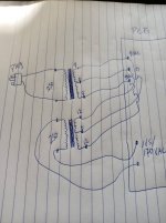
An alternative is to use a 9-0-9 50VA connected for the heaters, then also drive a 24V (12-0-12) to 230V 20VA in reverse from the same 9-0-9 to step back up to around 170V.
Someone draw it out for me please.
Perhaps ask a mod to fix the spelling mistake?Bigbottle Phonostage Bulders thread.
Ffs [emoji1787][emoji1787][emoji1787]Perhaps ask a mod to fix the spelling mistake?
Wait.....you mean you can do this with a relatively common, off the shelf traffo????Yes. Power supply is completely on board, only the transformer is off board.
An alternative is to use a 9-0-9 50VA connected for the heaters, then also drive a 24V (12-0-12) to 230V 20VA in reverse from the same 9-0-9 to step back up to around 170V.
Someone draw it out for me please.
Thanks for creating this thread! Would be amazing if folks who got their PCBs and are building currently capture their process - this will help a lot folks who are on last GB. 😉
Thanks Bas.
Two transformers, so probably more cost.
No need to connect the -0- of the 12-0-12 winding.
So could be a 24/230 20VA transformer.
Two transformers, so probably more cost.
No need to connect the -0- of the 12-0-12 winding.
So could be a 24/230 20VA transformer.
But the added bonus of a quieter supply. Or will the rectifiers make more noise?Two transformers, so probably more cost
Sorry Oliver, only saw this now, after you pointed me in the correct direction.
So I will have the toroidal made up for me to the following spec:
1 x 235 V primary (that's my supply voltage)
2 x 9 V @ 2A each secondaries (correctly phased, connected at the centre point)
1 x 170 V @ 200 mA
With elecrostatitc shield.
Wound onto a 100 VA core
Will be in an external metal case with fully shielded HV and LV umbilicals, fortunately also already have the correct cable too.
I already have a quote for the equivalent of $35 delivered.
That's a very good priceSorry Oliver, only saw this now, after you pointed me in the correct direction.
So I will have the toroidal made up for me to the following spec:
1 x 235 V primary (that's my supply voltage)
2 x 9 V @ 2A each secondaries (correctly phased, connected at the centre point)
1 x 170 V @ 200 mA
With elecrostatitc shield.
Wound onto a 100 VA core
Will be in an external metal case with fully shielded HV and LV umbilicals, fortunately also already have the correct cable too.
I already have a quote for the equivalent of $35 delivered.
Sorry Oliver, only saw this now, after you pointed me in the correct direction.
So I will have the toroidal made up for me to the following spec:
1 x 235 V primary (that's my supply voltage)
2 x 9 V @ 2A each secondaries (correctly phased, connected at the centre point)
1 x 170 V @ 200 mA
With elecrostatitc shield.
Wound onto a 100 VA core
Will be in an external metal case with fully shielded HV and LV umbilicals, fortunately also already have the correct cable too.
I already have a quote for the equivalent of $35 delivered.
Where did you find this? Please, share you sources! 😀
I doubt if is going to be more quiet, step up transformer with rectifier acts like an on/off switch which could add bit more noise to already noisy heaters , it would need to be tested in real life.But the added bonus of a quieter supply. Or will the rectifiers make more noise?
My thoughts exactly. Initially I saw extra isolation of the transformers...thinking...mmm quieter. Then I realized you'll have switching noise introduced into the HT primary.I doubt if is going to be more quiet, step up transformer with rectifier acts like an on/off switch which could add bit more noise to already noisy heaters , it would need to be tested in real life.
But anyway...by hacking the board you can supply the heaters any way you like.
Last edited:
I'm planning to bypass the on board supply with a 21st century regulator eventually for the high voltage part.
- Home
- Source & Line
- Analogue Source
- Bigbottle Phonostage Builders thread